What the owner wanted
An 1800s three-family in Mystic that the owner is renovating in phases with Tidal Build: the basement first, then a new roof with a raised third-floor ceiling and dormers, then the first and second floors. He asked for three things, and the letter is organized around them. What condition the house is in as a whole. A specification for the basement framing work that he could hand to a framer and start from. And a structural opinion on whether the third-floor plan can be carried, written so the basement work prepares for it.
Matt Williston at Tidal brought me the job, sent his schematic basement plan and twenty photographs of the basement ahead of time, and met me there for part of the visit.
What we found
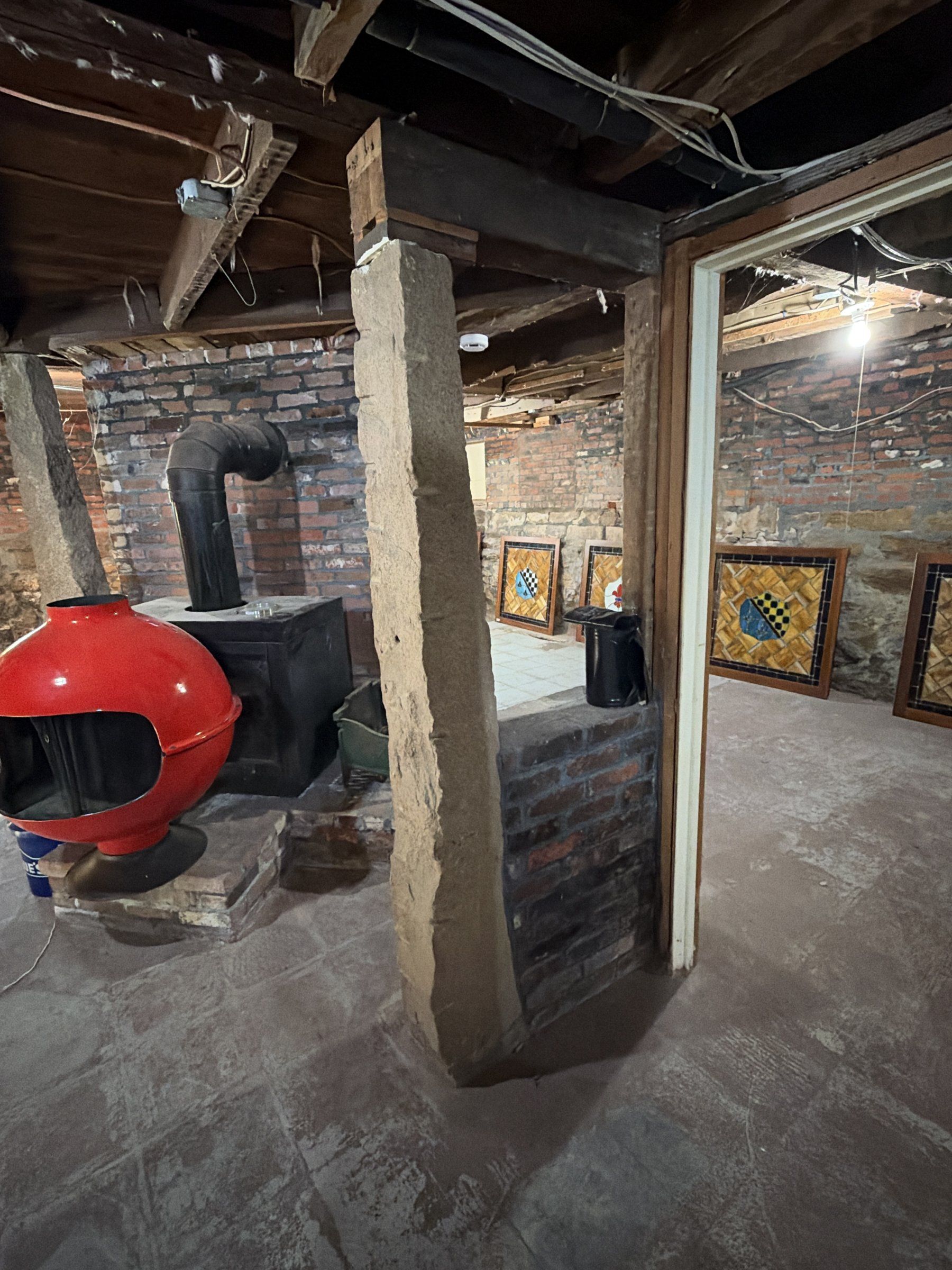
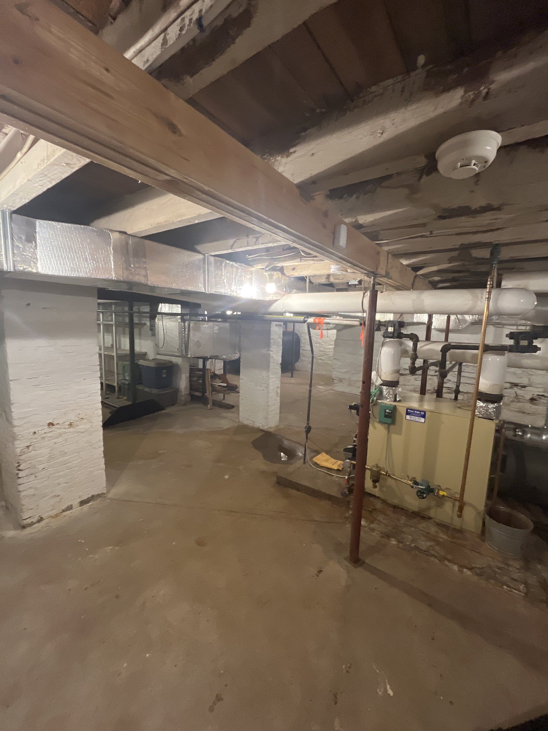
A three-story wood-frame house about 45 ft along the street and about 22 ft deep, with a wrap-around porch, a gable roof with the ridge running parallel to the street, and a chimney at the left gable end. The foundation is brick over a band of stone, whitewashed inside, with brick piers built against the walls and a slab floor. The basement ceiling had already been opened to the framing, so all of it was there to see.
The first thing the basement tells you is that the house is balloon framed. The sill does not sit on top of the foundation wall. It runs against the inner face of the brick and bears on the piers. That matters later, when a ridge-beam post needs somewhere to land at each gable end.
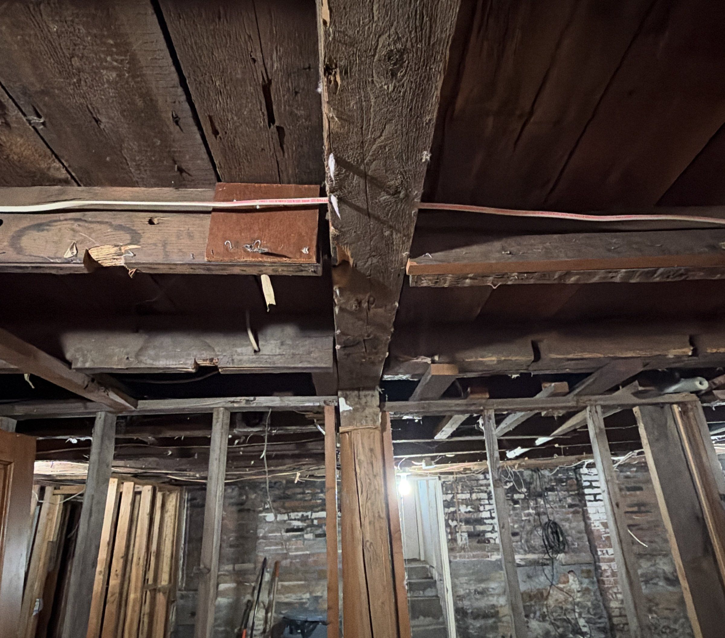
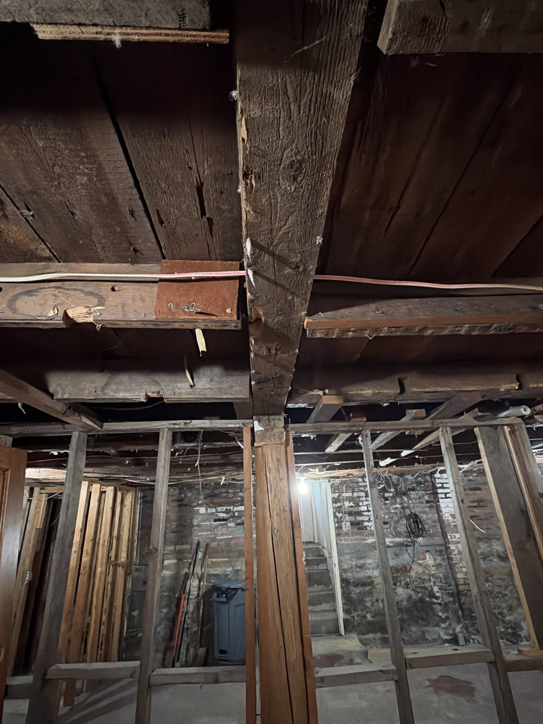
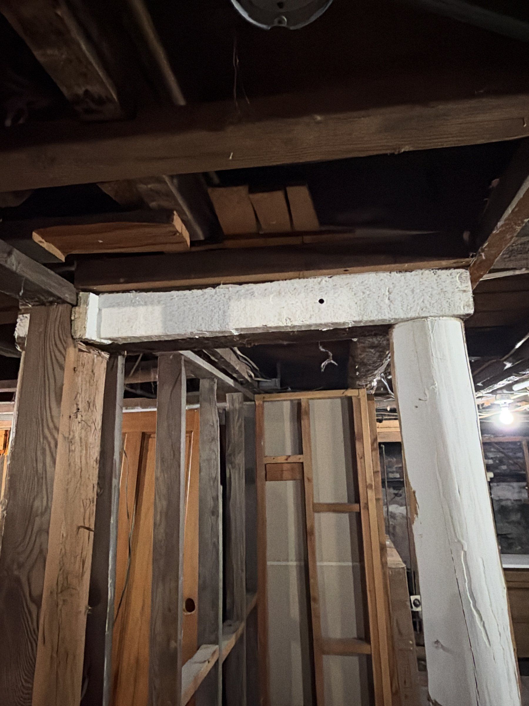
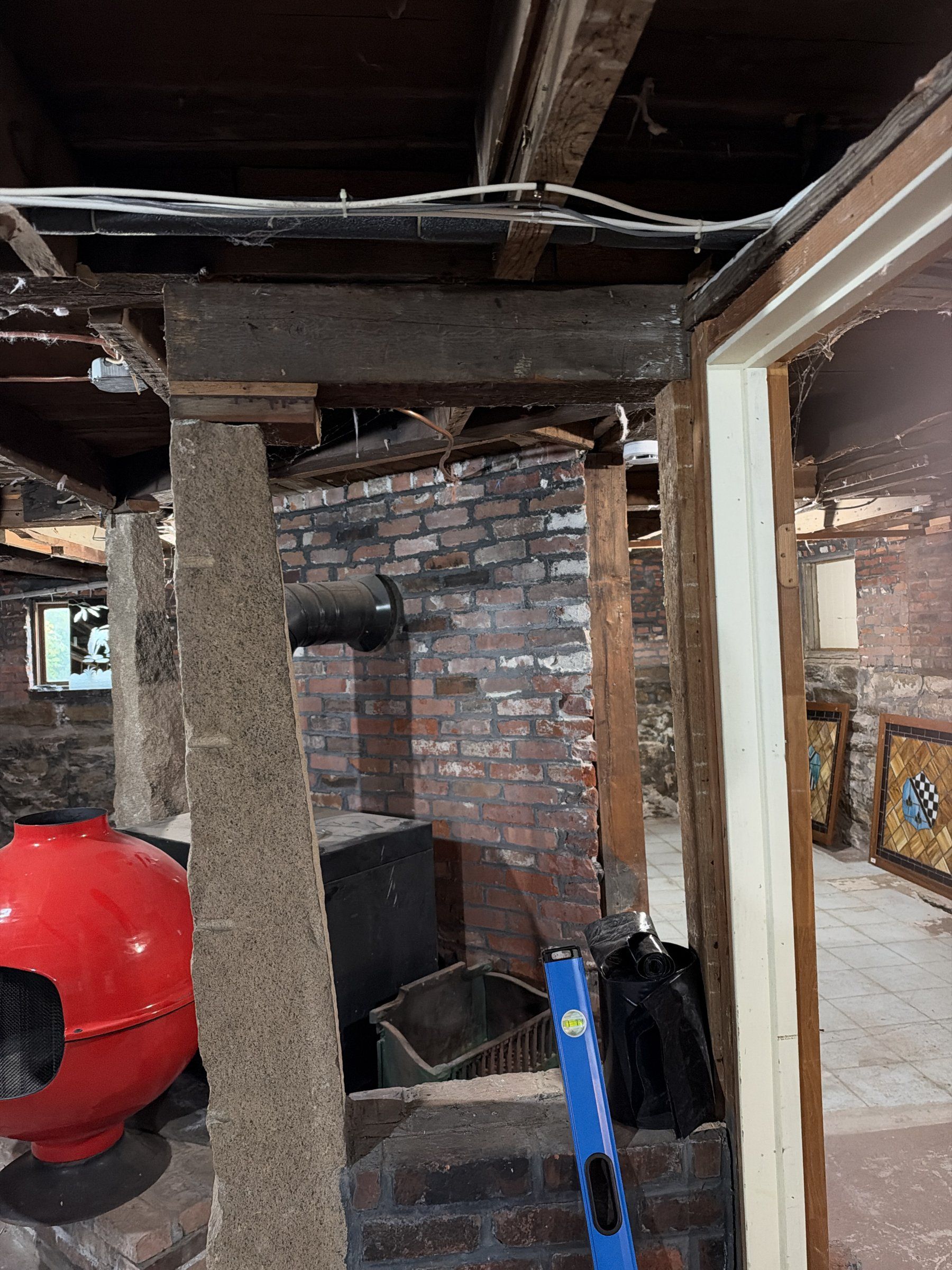
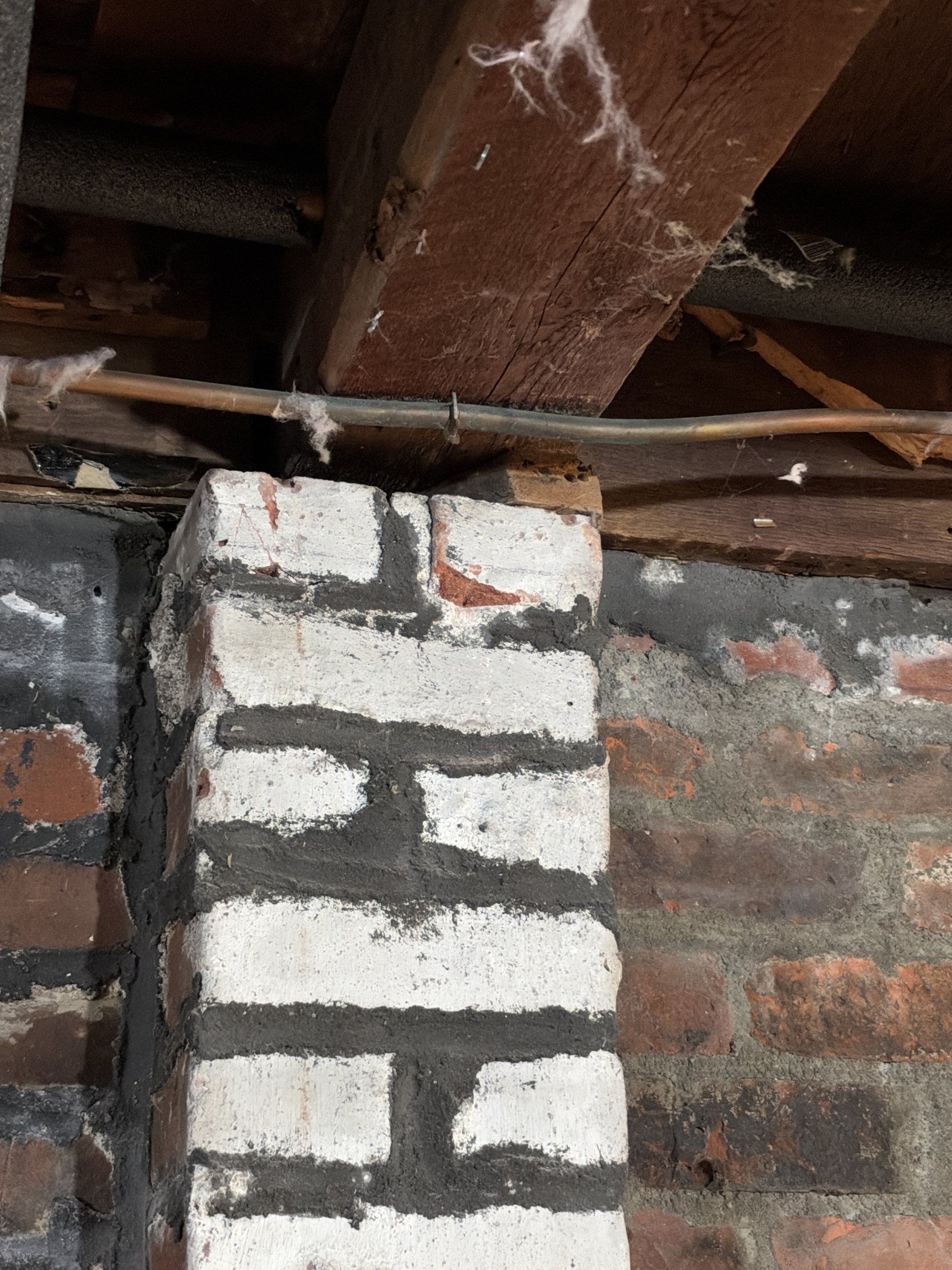
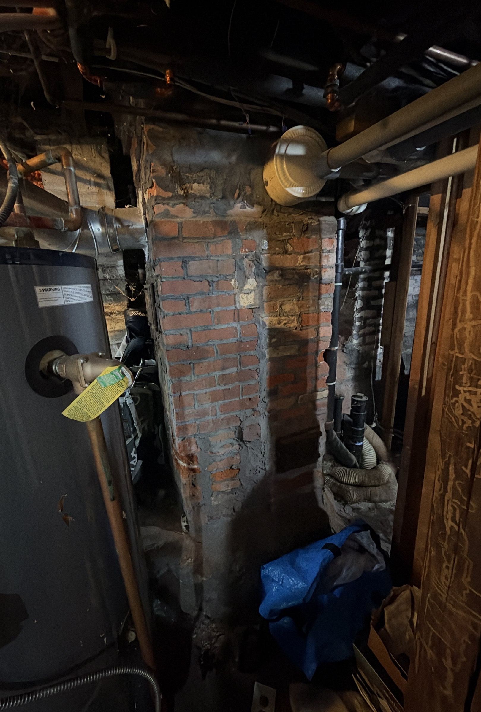
The first floor is rough-sawn joists on 6x6 girders that run front to back across the basement, from eave wall to eave wall, each one about ten and a half feet from the wall to a support at mid-depth. Those mid-depth supports are the story. The original ones are two tapered granite posts, a single stone each; post 2 is 9 in at the base and about 5 in at the top. Everything else is a later generation of repair: a built-up wood post beside one granite post, two posts carrying a makeshift header of two pieces of wood and a stack of shims under one girder, a 6x6 and more shims bearing on another beam under a second, and at one pier a girder end sitting on a shim that does not fully cover the pier. None of the later supports stands on a footing I could see and none is fastened top and bottom.
On the letter’s assumptions, a 6x6 under this floor wants supports about five feet apart or less. Where it is more, the girders have sagged over the life of the house. Along two of the girders, on the front half of the house, where the joists are joined with mortise and tenon and no hangers, the tenons have pulled part way out of their mortises as the girders dropped away from them. Every floor above slopes inward toward the middle of the house, which the owner confirmed and which I walked.
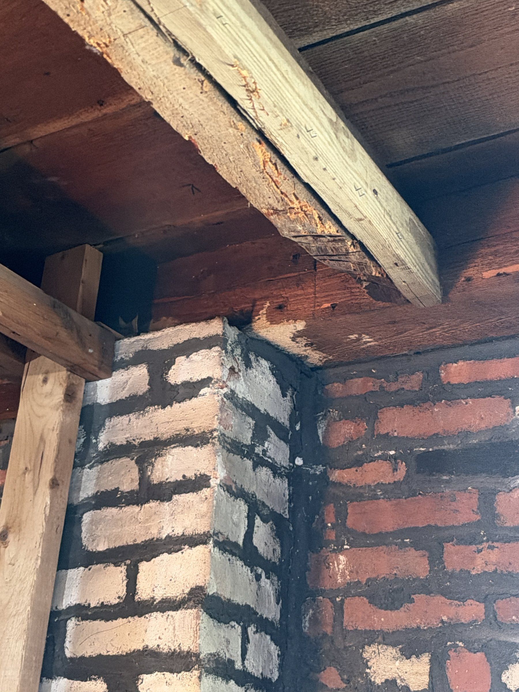
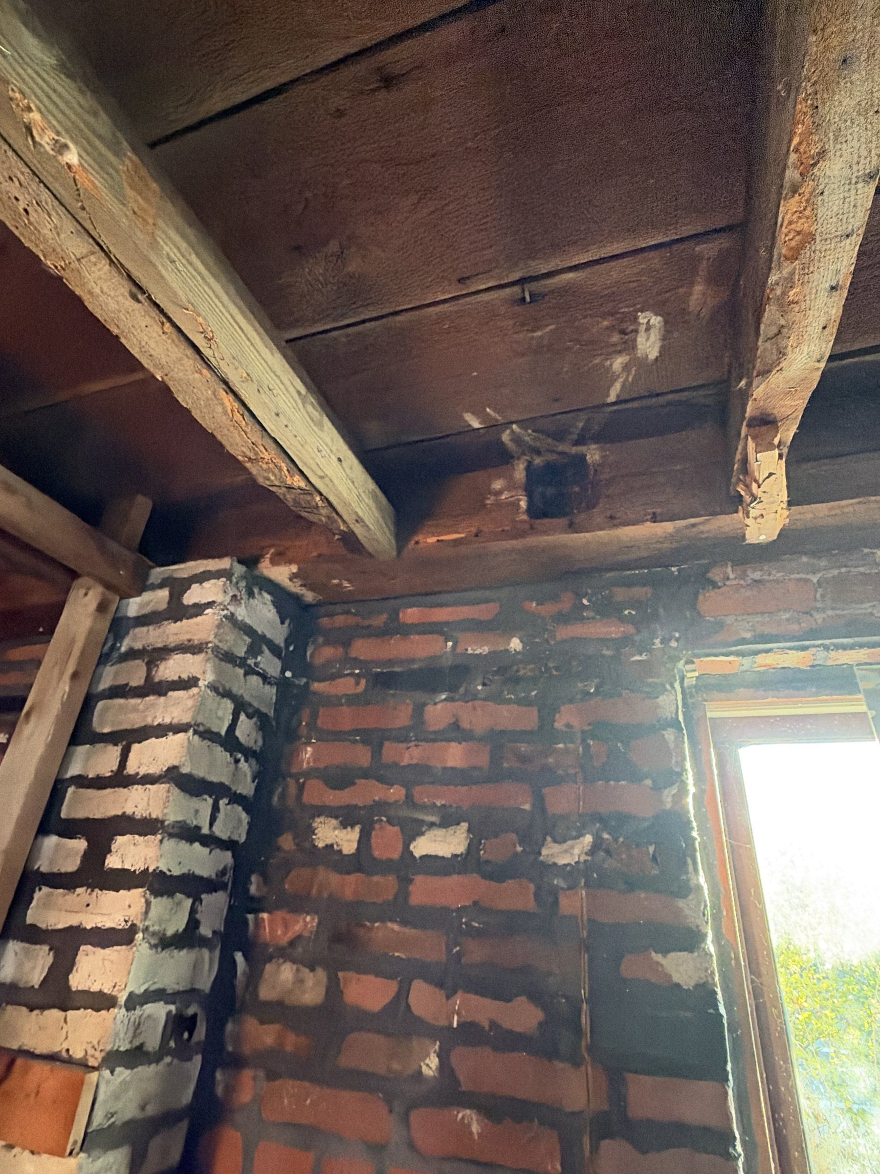
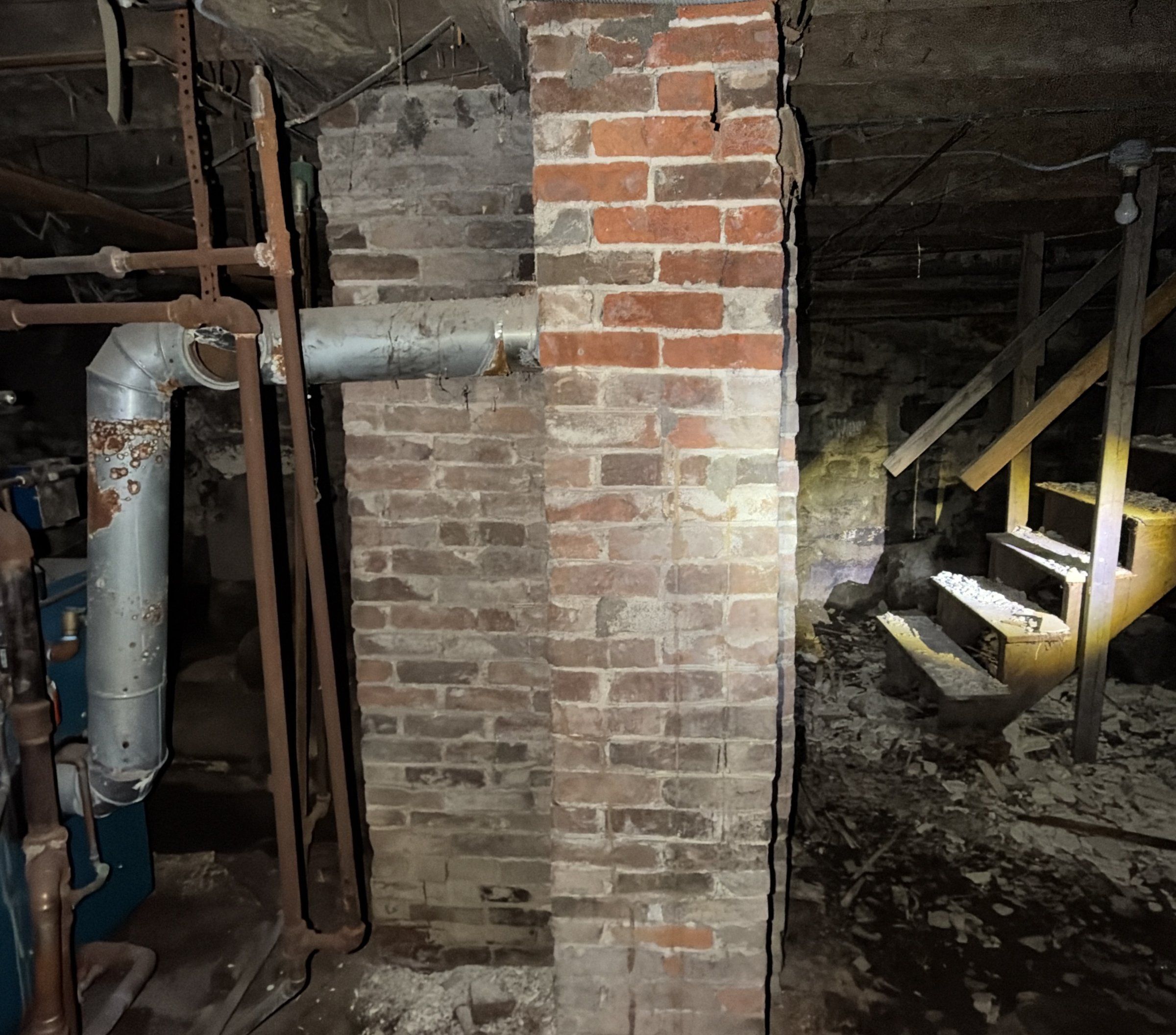
The wood itself is fine. Pin readings at the girders were 9 to 13 percent, dry for a basement, and I found no active rot anywhere in the basement framing, no decay at any support, and no sign of water coming in. The only damage of note is a big old notch in the sill beside one pier, probably cut for a pipe, with a hole in the floor above it, and what may be old insect damage in one or two joists beside it. The piers are sound, the chimney stands on a mass of concrete, and the foundation walls show nothing worse than minor spalling. Stone does not creep. The sag is in the wood between the supports, not in the posts, and nothing in the basement suggests the foundation is moving.
The engineering
The fix is support and connection, not replacement. Give every girder a permanent post on a real footing at close enough spacing that it cannot sag further, take the load off the shims and the improvised headers, replace the shims with steel plates, and put a hanger on every joist that has walked out of its mortise. Done in that order the floor stops moving and the joints stop opening.
The specification is nine numbered items a framing contractor can price from the letter, and the post layout was then set girder by girder in Addendum 1, signed and sealed November 8, 2026, from the measurements the contractor took on November 6. The addendum replaces the letter’s items 1 and 3 and governs where the two differ; everything else in the letter stands. Each girder is checked first. A brick pier or a granite post is its middle support only if it stands under the girder near its middle, the girder sits right on it and not on a header or shims, and it is sound, plumb, with no crack through it and hard mortar; every other girder gets a new middle post. Then the side posts, from each eave wall to the middle support, with no gap longer than the girder’s largest gap. The letter’s five feet took each girder as 6 in square with the bays unmeasured; the addendum, set from the contractor’s tape of the girders and the bays between them, gives each girder its own largest gap: 6 ft 6 in on girder 1, 6 ft 0 in on girder 2, 4 ft 6 in on girder 3 and 5 ft 6 in on girder 4, numbered from the chimney end, and no gap over 3 ft 6 in on a girder whose joist pockets are cut open through its top. At the lengths on the plan that is 10 to 14 side posts in all, plus the new middle posts.
Each side post is the letter’s item 2: a 3-1/2 in Schedule 40 steel pipe with welded plates, or a manufactured adjustable column listed for permanent use, on its own footing cast below the slab, 24 in square by 12 in thick with three #4 bars each way, set with a temporary shore beside it, the girder lifted only until it bears on the post, then the shore released. Where a girder gets a new middle post, the middle is carried before the slab is cut: a temporary beam under the girder across the area to be dug, with a shore at each end outside the cut, sized by the contractor to carry 21,000 lb, the same load as the new post, and whatever props the girder there comes out only once that beam carries it. Then the footing, 48 by 48 by 14 in of 3,000 psi concrete with seven #4 bars each way, dug to undisturbed soil or cleaned ledge and never fill; then the post, a 3-1/2 in adjustable steel column with a 0.216 in wall, rated for at least 21,000 lb at its installed height, under an 8 by 10 by 5/8 in steel plate lagged to the girder. No post takes load until its footing is 7 days old, and the work goes one girder at a time.
At every pier or post top where a girder bears on wood shims, the shims come out and a 1/2 in steel plate the full width of the girder goes in on a bed of non-shrink grout, so the girder bears on steel on grout on solid masonry. At every joist whose tenon has pulled, a face-mount hanger listed for 2 in rough-sawn lumber, every hole filled, installed after the girder is on its new posts with the joist drawn tight so the hanger carries it from the day it goes in.
The joists are a separate question. They are reported as about 2x6 at about 24 in, and I did not measure them. Rough 2x6 joists at 24 in are, by calculation, lighter than today’s code wants for a residential floor at spans of ten feet and more; in the narrower bays toward the chimney end they are closer to it. The contractor’s tape on November 6 later put them at 2 by 6-3/4 in at 24 in on center. The house has stood on them, and left exposed and watched they are acceptable as they are. If the basement is to be finished with an insulated ceiling under rented bedrooms, I recommended sistering every joist with a 1-3/4 by 7-1/4 in LVL, full length, which brings the floor to a modern stiffness and costs mostly labor, and the letter sizes it so the contractor can price it. The contractor has since measured the bays; every one is under 12 ft, so no sister needs the 9-1/4 in LVL.
The historic slope is accepted on purpose. Jacking the house back toward level after a hundred years would crack plaster and finishes on three floors for no structural gain.
Does the knee wall have to be there?
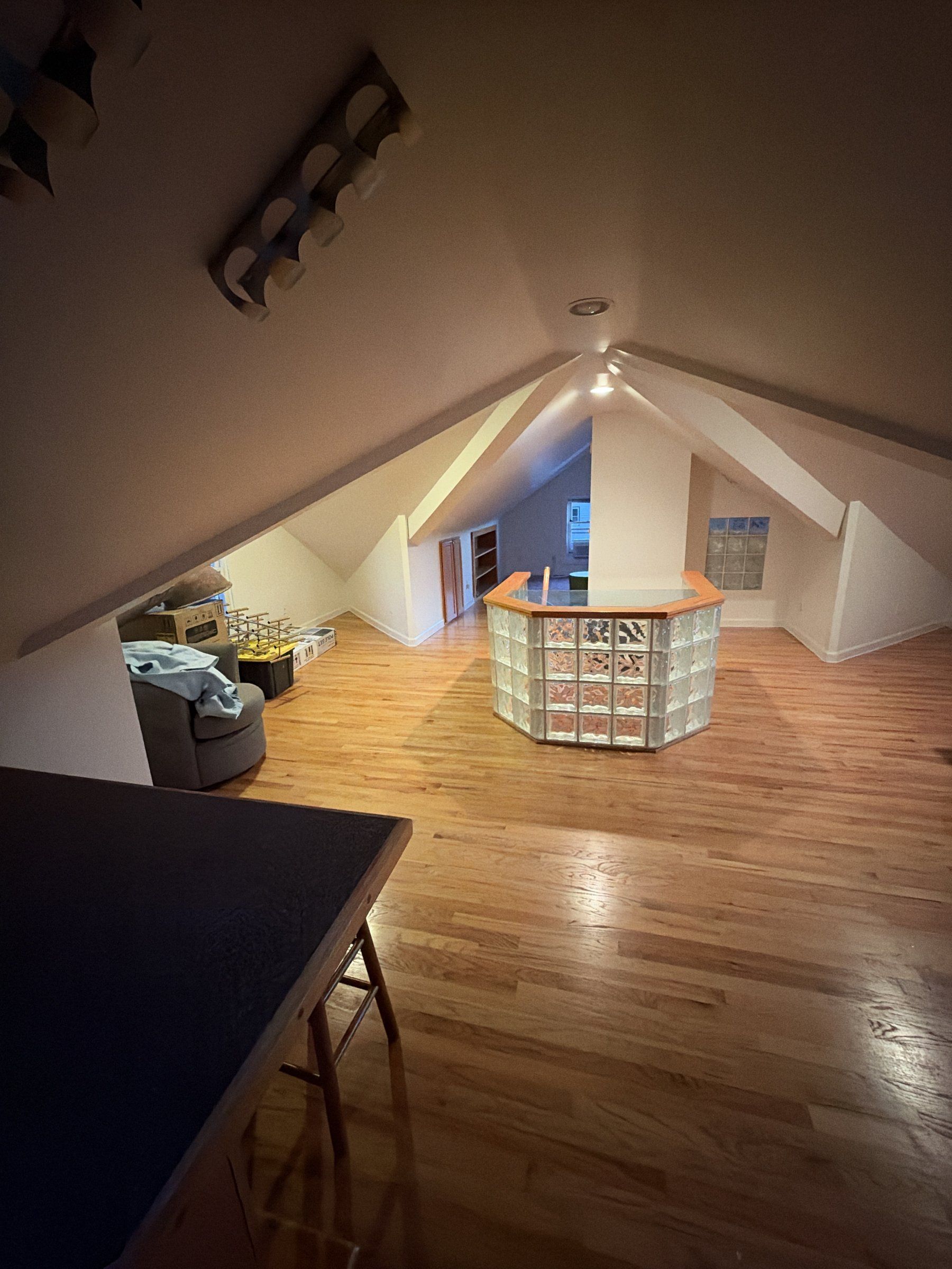
The third floor. The owner intends to take the roof off, raise the ceiling to about 10 ft, keep the front gable dormer and add two more beside it, build two gable dormers joined by a shed dormer on the rear slope, and keep the front facade as it is. Structurally this works. The way to do it is a continuous ridge beam between the gable end walls on three posts: one at each gable end and one intermediate post near the middle of the house. With a ridge beam the rafters hang from the ridge instead of pushing on the eave walls, so the knee walls and ties that hold an ordinary gable together are no longer needed and the ceiling can open up. Without the middle post the beam would span about 45 ft and be deep and expensive. With it, each span is about 22 ft and the beam is a reasonable engineered lumber or steel member.
On a planning basis, under Connecticut snow, each gable-end post carries on the order of 5,000 lb and the intermediate post on the order of 16,000 lb. The end posts can land on the existing masonry, on the pier at the right gable end and in the space behind the chimney at the left, about 9 in clear, through a steel plate on the brick in each case. Whether the ridge falls exactly over that pier and the chimney, or a foot or two off, is a survey question for the design phase; if it is off, a new pier beside the existing one takes the post. The intermediate post is the one to plan for. It has to pass through the third, second and first floors to a footing of its own in the basement, about 4 ft square, on the centerline of the house where the girders’ mid-depth supports stand. It must not land on a girder between posts and it must not land on the slab. The new middle footings and columns of the basement work carry the floors only; the ridge post does not land on them without a new design. The obvious place to hide it is the stair and closet stack at the middle of the house, which is why the third-floor stair and this post should be settled together in the design. That is also why the new basement partition on the plan, which sits about two feet off the centerline, is a partition and not a bearing wall. If the owner wants it to carry the ridge post, it moves to the line of the supports and the post gets its own footing there.
Working with the design team
Tidal Build designs and builds its own work out of Mystic and keeps no engineer on staff. Matt draws, with a good feel for how a frame carries its load, and the calculations and the seal are mine. On this one the owner wanted the whole house looked at and a specification he could build from before Tidal’s drawings existed, so the letter is written to be built from directly and to hand the design phase a basement where the ridge post has somewhere to land.
If you own an old house along the shoreline and the floors have gone soft or the plan has a bigger roof in it, this is a job I do. One visit, a letter that says what is sound and what is not, a specification your framer can price, and the design after it when you are ready.
This page describes engineering performed for a specific structure under conditions verified on site.
Spans, member sizes, and connection details are particular to that building and its
loading. Nothing here is a design for any other structure. Every project requires its own
analysis by a licensed engineer.