What the builder wanted
Tidal Build, a design-build firm in Mystic I have worked with before, brought me a seven-sheet permit set for a residential elevator addition on a 1951 cape in Dover, Massachusetts. The owner wanted a home elevator running from the basement to the first floor. That meant a small hoistway bumped out the back of the house, about 4 ft 7 in by 4 ft 9 in inside, a small control room beside it, new foundation walls, a raised roof section over the hoistway, two new doors and a relocated window in the existing rear wall, and a pit cut into the basement slab.
Most of the structure was already on the set. What Tidal needed was an engineer to review the structural content, design the items the set left open, and seal it for the building department. I practice in Connecticut and held a Massachusetts temporary permit for this project.
What we found
Reading the set produced the usual short list for the kickoff call: which ridge LVL and rafter spacing the architect wanted where two sheets differed, where the structural general notes would live, and the elevator manufacturer’s loads, which no permit set carries until the elevator is picked. We settled those on a recorded call. What the set could not tell anyone was what was under the house.
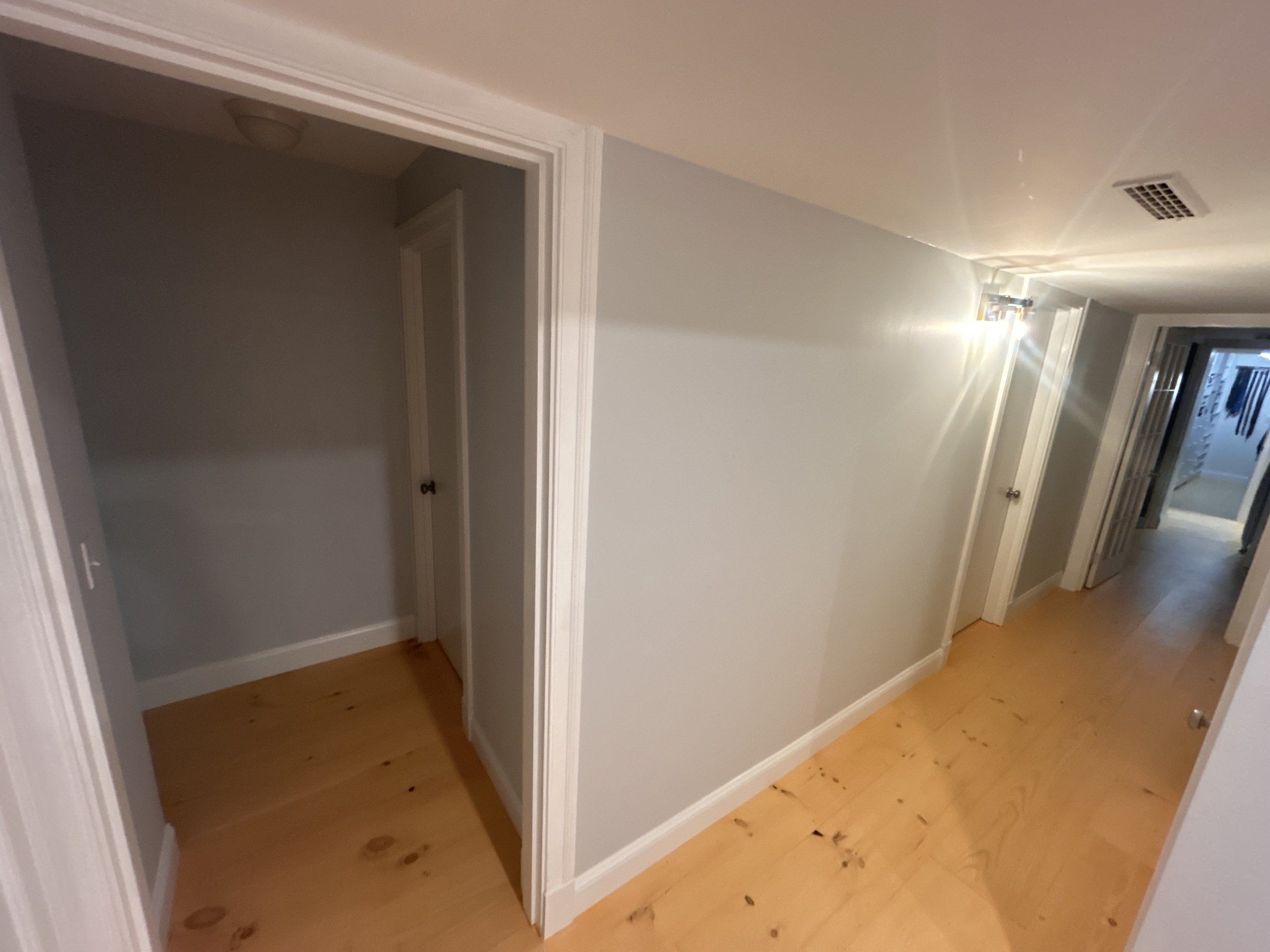
That last one mattered most. The ridge beam over the new roof lands on two posts, and those posts land on an interior bearing wall that the drawings neither show nor dimension. Below that wall is a basement carrying beam, and the basement is fully finished with a flat drywall ceiling. Nobody could see the beam.
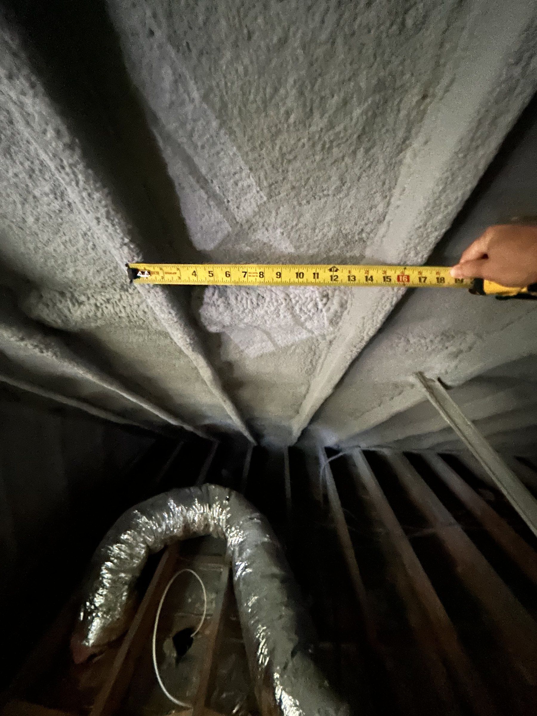
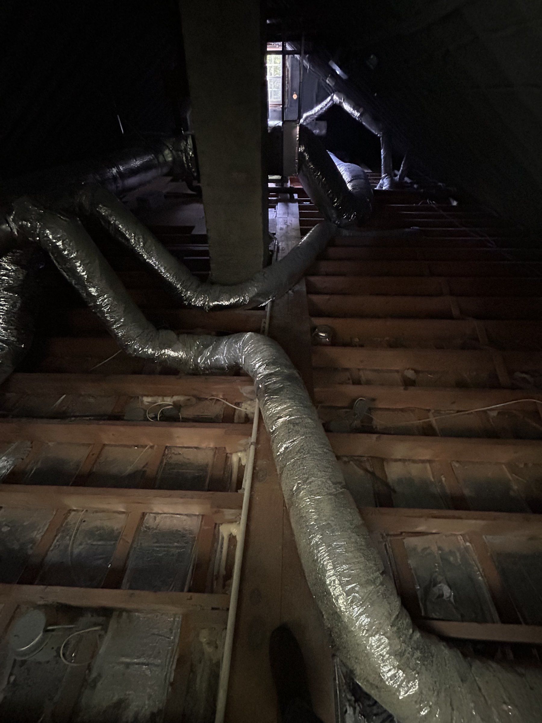
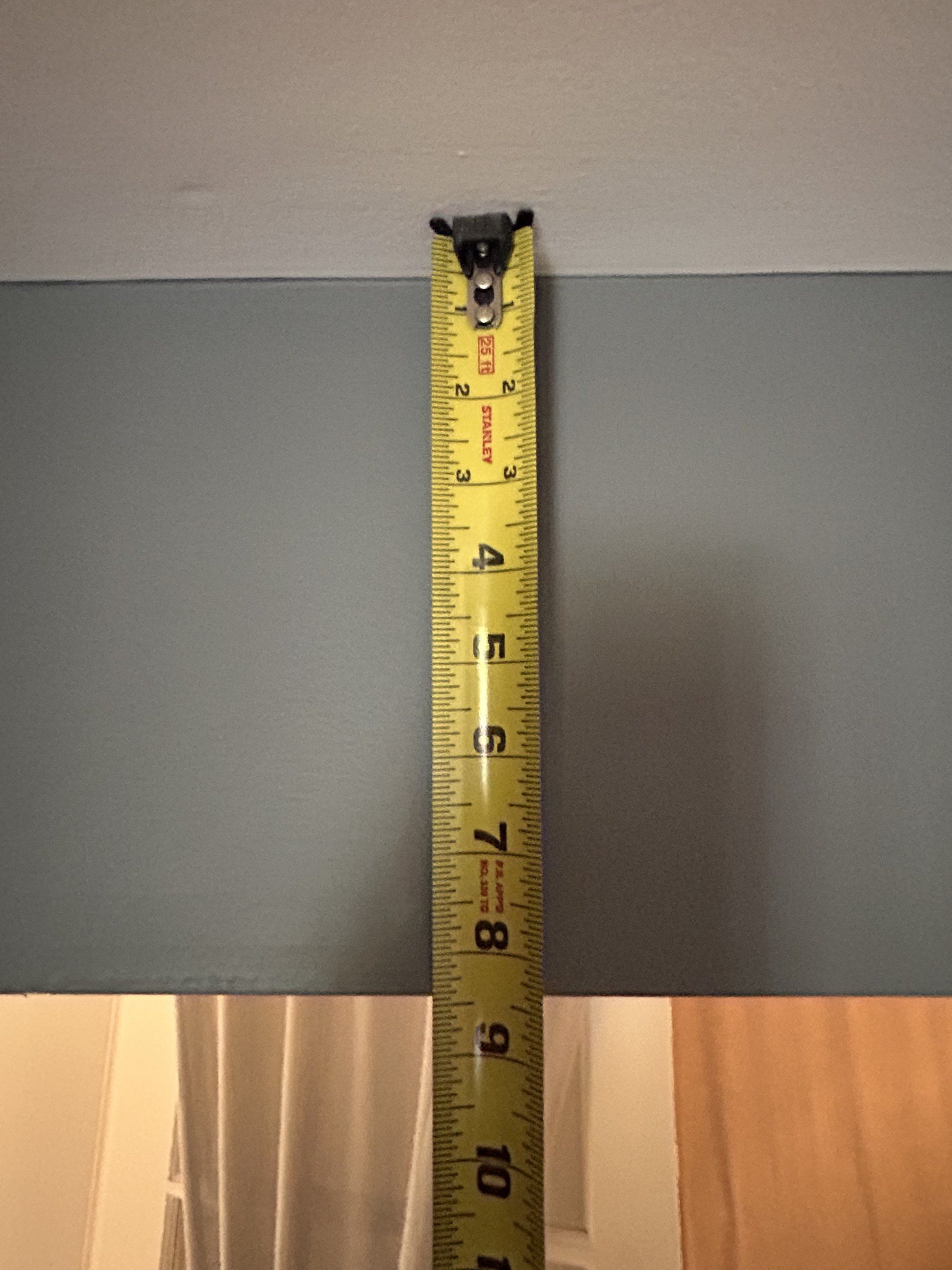
The contractor did the legwork. He found a dropped box in the ceiling running along the center line of the house, in line with the ridge and with a bearing line visible at the attic floor. He taped the box at a doorway and came back a day later with a magnet. No pull anywhere, so wood and not steel. The box bears on short wall segments between a line of cased openings and doors, and it stops about 17 ft short of the far wall. Which end of that run the elevator corner sits on could be read from the plans and the photographs, but only as an inference, and the beam itself, its size, span and condition, was never measured.
The attic had its own surprise. Every rafter was buried in spray foam, so the size and spacing the set relied on could not be confirmed from any photograph.
The engineering
The design was written so that none of those unknowns had to be resolved before sealing.
The new roof is a raised 5:12 section standing over the existing roof, closed on each side by a short triangular wall. The new 2x12 rafters at 12 in o.c. span 20 ft from a three-ply LVL ridge beam down to the outer hoistway wall. The drop beam the set drew at the line of the old rear wall is made non-bearing, so the new roof puts no load on the 1951 wall. On each side, the existing rafter under the triangular wall gets a 2x10 sistered full length, and so does the next rafter out, which takes the snow that drifts against the wall. The builder had floated a knee wall on a tripled rafter. The sealed design uses a doubled one.
The ridge beam posts are 3-1/2 x 5-1/4 in PSL, placed in the field directly over the bearing wall once the contractor has found it from the attic. The letter spells out what that wall has to be: continuous in one plane from the second-floor plate to the basement beam, solid blocking through every floor so the joists are never in the load path, and at least two full-height studs under each post at each level. The contractor confirms it in writing with photographs before the beam is loaded. That is an ordinary pre-framing confirmation of an existing condition the drawings do not show, not a condition on the letter.
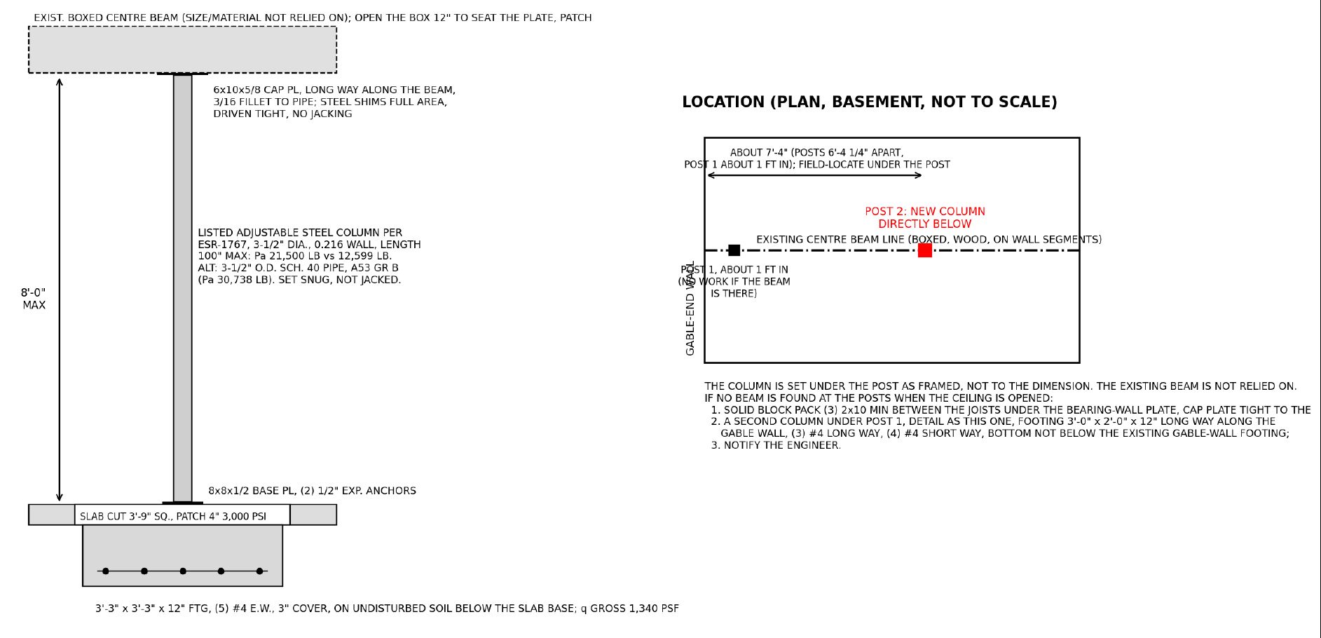
Under the second post goes a new 3-1/2 in steel column on a 3 ft 3 in square footing, cut into the slab, its cap plate set tight to the underside of the existing beam without jacking. The point is that the existing beam’s size, span and condition are never relied on. If no beam is found at the posts when the ceiling is opened, the sheet says what happens instead: block solid up to the first-floor wall, add a second column under the first post on a footing no deeper than the gable wall footing, and call this office.
The rest of the package is the kind of detail an elevator addition needs and a permit set usually leaves out. Two new door openings and a relocated window in the rear wall, on (2) 2x10 headers, with the wall treated as bearing for the full roof, attic and upper floor. New 10 in foundation walls on 2 ft footings, 48 in below grade, doweled into the 1951 wall with No. 5 epoxy anchors at 16 in, with an underpinning detail for the case where the old footing sits more than 12 in above the new one. The control room walls retain the uphill grade and were designed as a closed box tied to the old foundation, good for a retained height up to 4 ft 6 in. The pit, the rail wall pads, the lifting beam and the hoistway shear walls all came from the manufacturer’s drawing and the wind and seismic numbers for the town.
Design snow was the Massachusetts flat-roof minimum of 35 psf on a 40 psf ground load. Wind was 120 mph, Exposure B. Seismic Design Category B.
How it got delivered
Kickoff call on a Wednesday, recorded with the architect’s consent, to settle the open questions in the set. Photographs and the elevator submittal arrived the next day, and the contractor’s basement investigation ran over the following week while the calculations were being written. The package went out twelve days after the call: a five-page letter, the redlined architectural sheets, S-1 and S-2, and the calculation book, all signed and sealed.
If you are an architect or builder with a set that needs a structural review and a stamp, that is a service line I run, and I am happy to look at a set and tell you whether it needs me before anyone spends money.
This page describes engineering performed for a specific structure under conditions verified on
site. Spans, member sizes, and connection details are particular to that building and its
loading. Nothing here is a design for any other structure. Every project requires its own
analysis by a licensed engineer.