
Load-Bearing Wall Removal in Newington, CT: One Beam for a 21 ft Line
- Town
- Newington, CT
- Service
- Load-Bearing Wall Removal
- Completed
- November 2026
- Delivery
- Site visit October 20, options letter sealed October 28, the permit plan set and structural letter signed and sealed November 2, 2026, four days ahead of the date promised
What the homeowner wanted
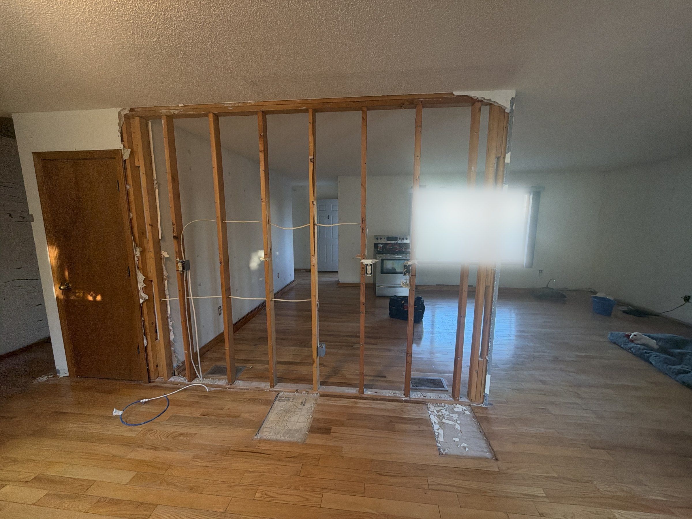
A 1988 ranch in Newington with the wall down the middle, running along the ridge between the kitchen and dining area on one side and the living room on the other. The owner wanted it gone for the open layout in his rendering. He had already pulled the drywall off the wall by the time I got there.
What we found
The wall is 9 ft 6 in long and it is bearing. The 2x8 ceiling joists from the front half of the house and the back half lap over the top of it, so it carries the ceiling and whatever is stored in the attic. Just as important, that lap is what ties the rafters together across the house. Cut the joists and you have cut the tie.
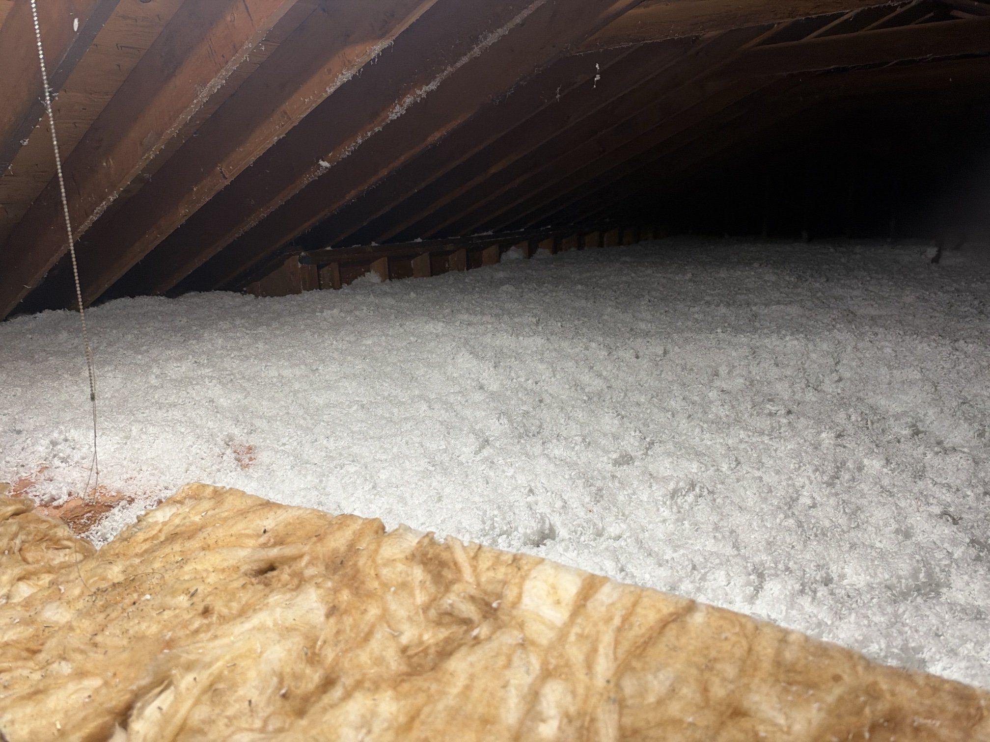
The bigger find was the part of the line that was already open. The 11 ft 9 in bay between the wall’s end and the fireplace had been opened years ago, and from the room it looked free. It is not. Up in the attic the owner found a header of three 2x6s above the ceiling, spanning that bay and sitting on the end of the wall he wants out. So the wall and the header come out together, and one beam carries the whole 21 ft 3 in line, from the brick fireplace on the garage wall to the wall beside the basement door.
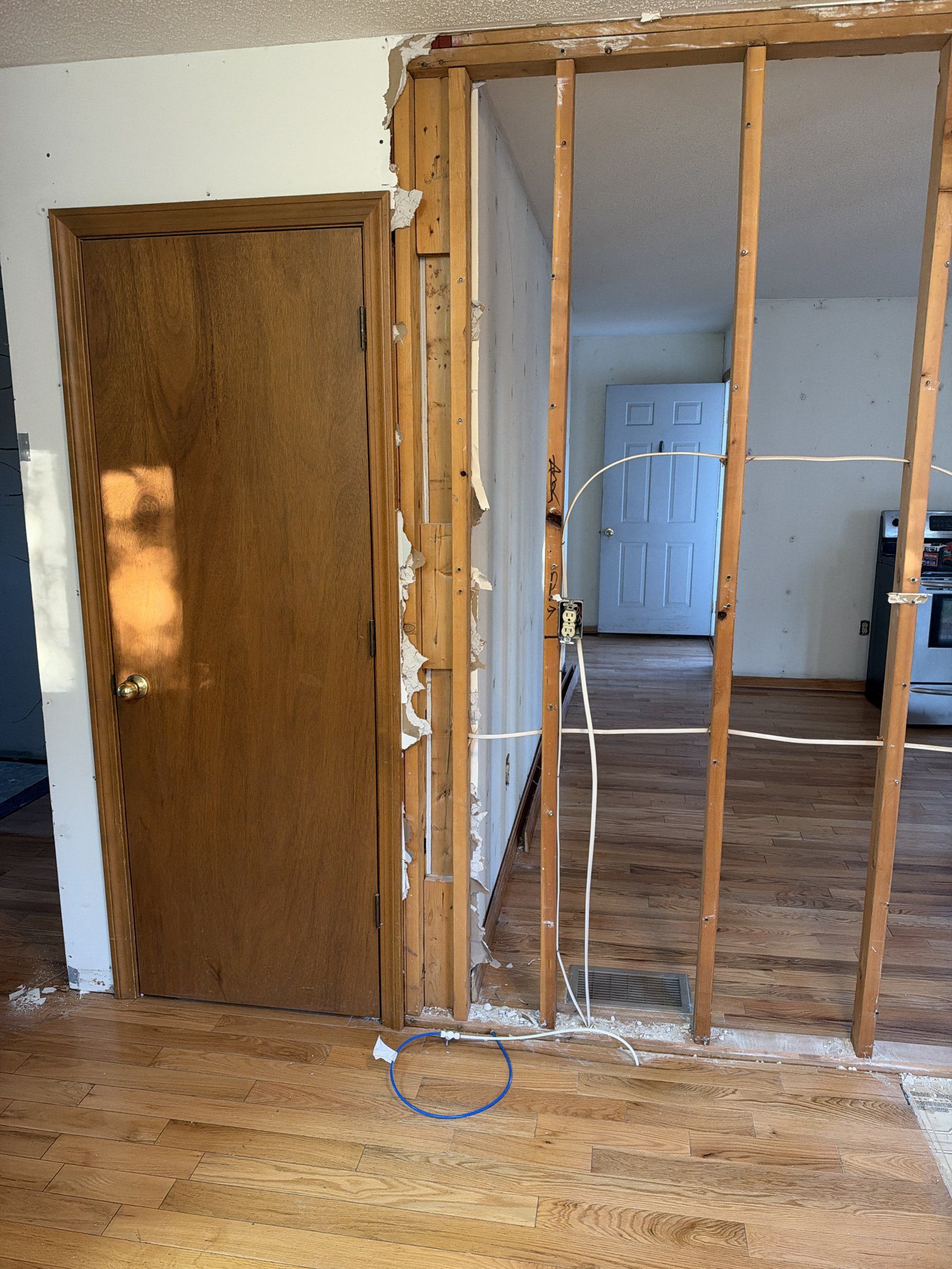
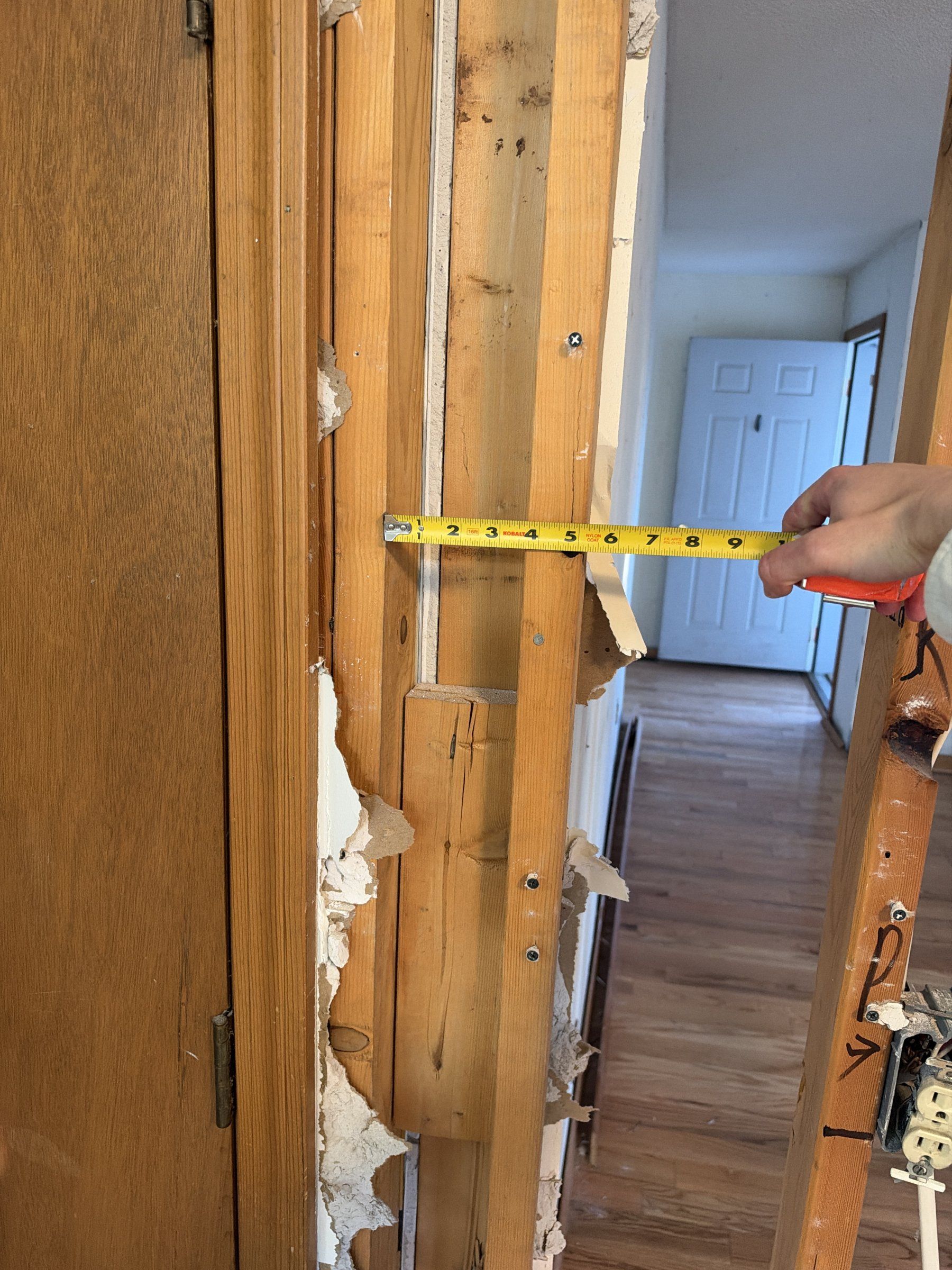
Then the two ends. At the basement door there is exactly 5 in between the door trimmer and the wall to fit a post, and the post has to live inside the wall because an island goes beside it. At the other end the fireplace sits exactly where the post wants to land. We agreed on two documents: an options letter first, then the permit set.
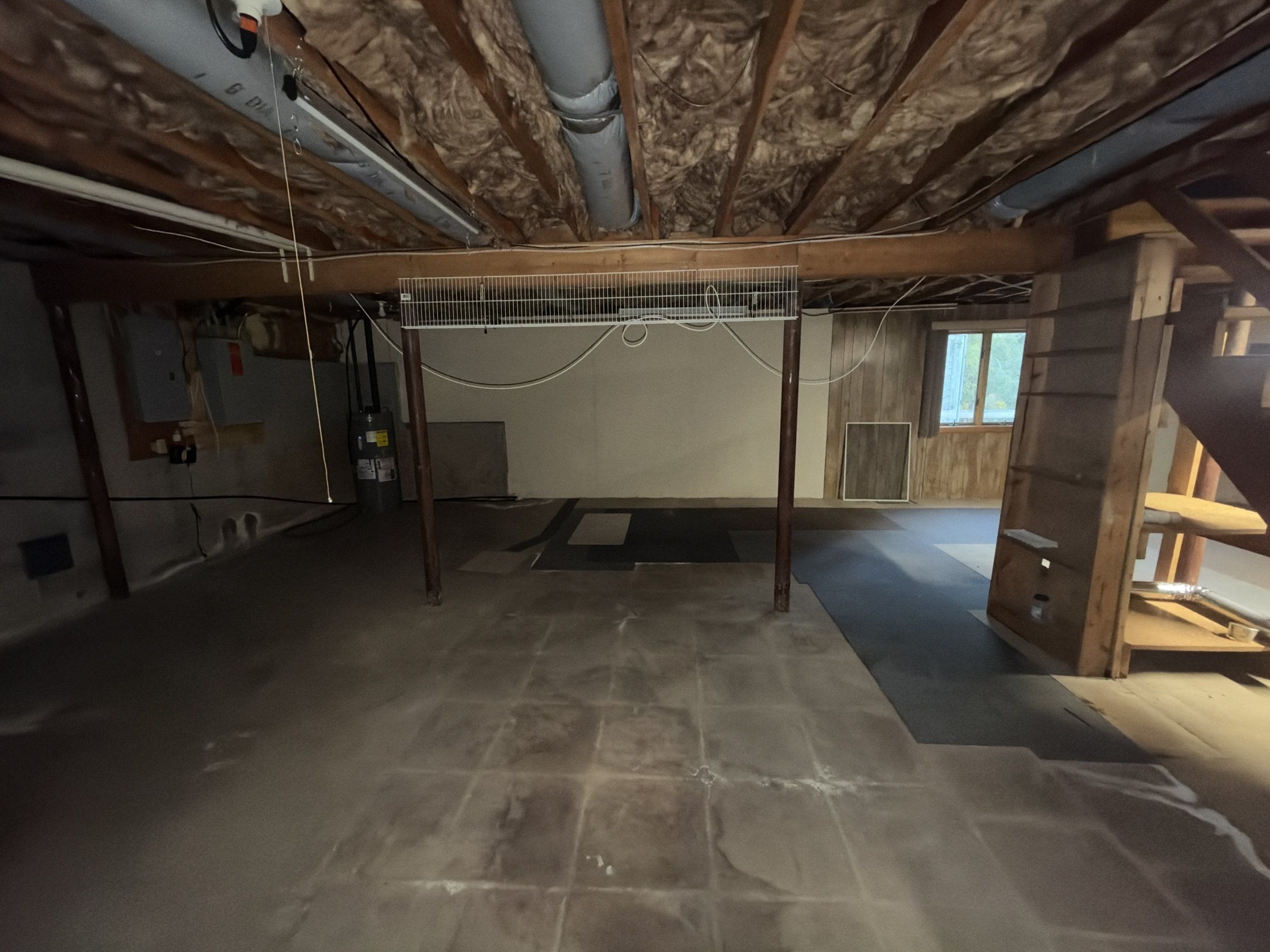
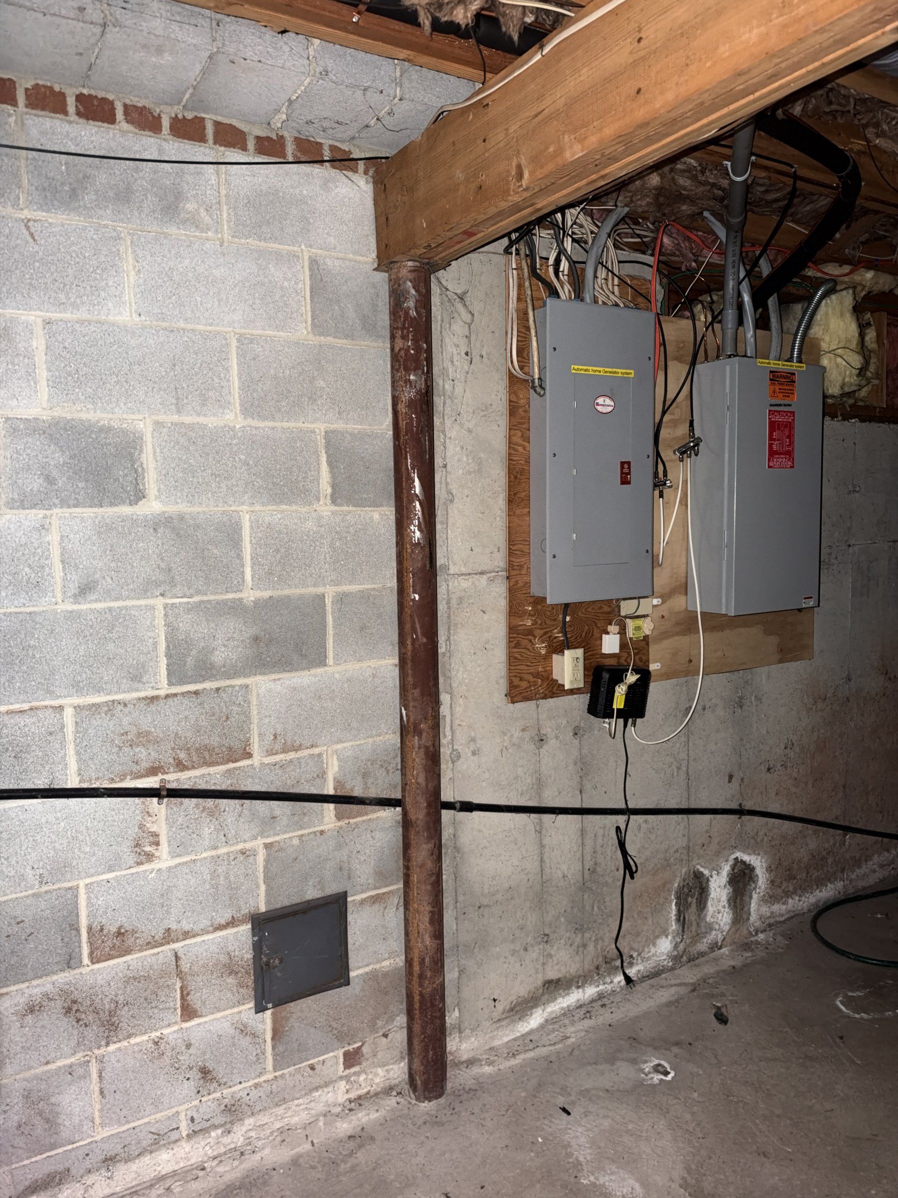
In the basement a built-up girder runs under the line on steel columns, with the first-floor joists sitting on top of it. I said on site that those columns would not be doing anything after this. Reading the photographs at full resolution corrected that: the girder carries the first floor whatever happens above, so it and its columns stay. There is no column under the spot by the basement door, only a shelf, so a new one goes there.
The engineering
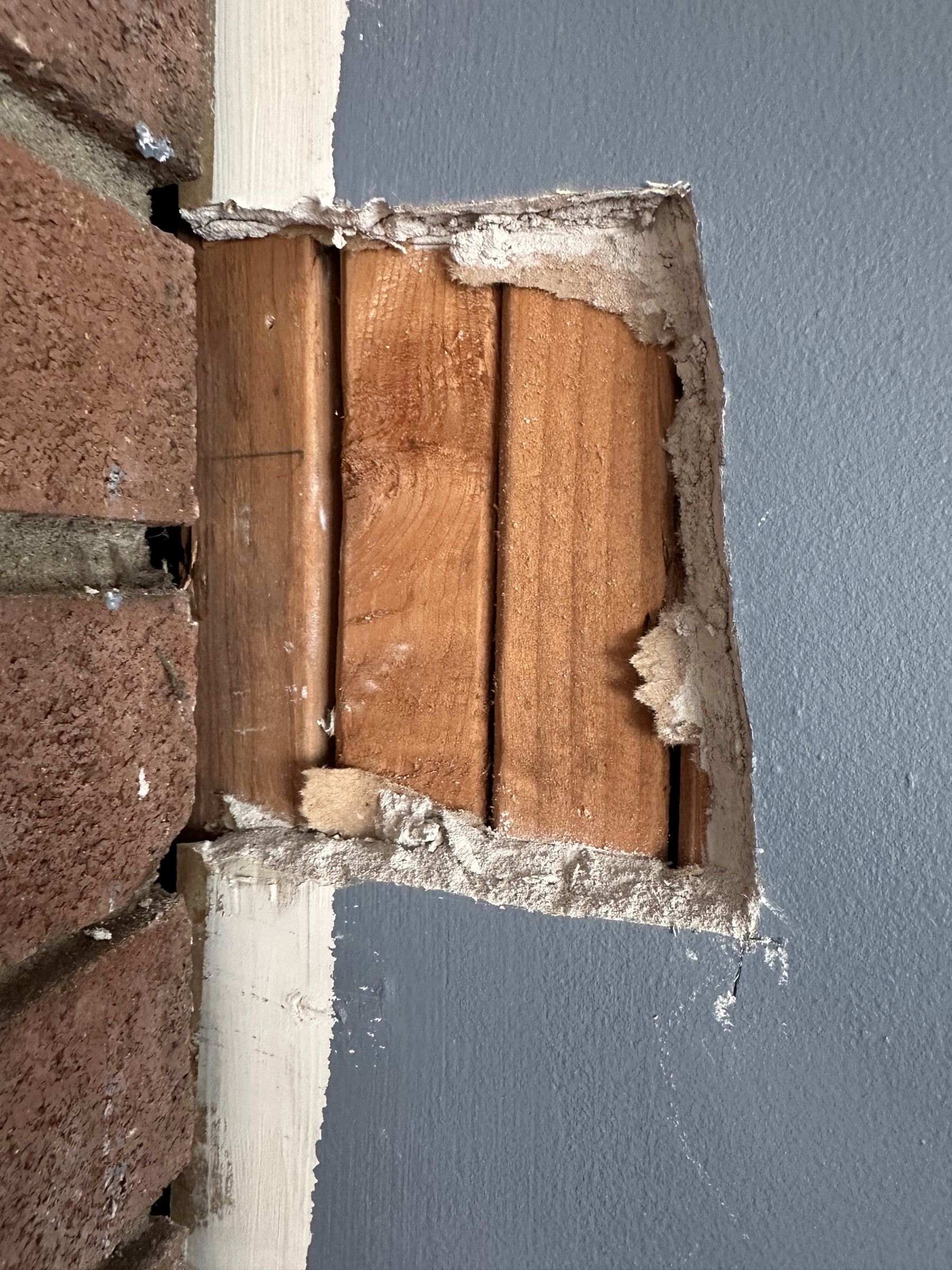
The options letter laid out two ways to do it, a beam for the whole line with no post in the room, or a shorter beam ending on a post at the island. Nine days after the visit the owner opened the wall beside the fireplace and photographed a stud pack against the brick. The day after, his contractor called and walked me through his plan: a steel post hidden behind the fireplace facade down onto the foundation wall, a new column and footing in the basement by the door, and an LVL beam up in the ceiling with the joists hung on it. That is the no-post option in LVL, and it is what the set draws.
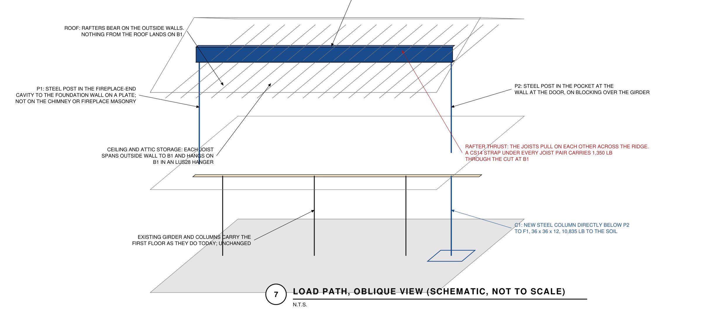
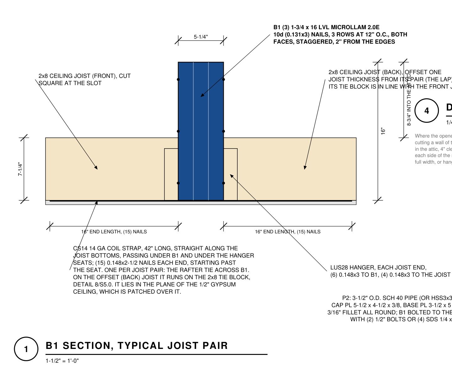
Beam B1 is three plies of 1-3/4 by 16 in LVL, set flush with the joist bottoms, standing 8-3/4 in into the attic. Every ceiling joist is cut at the beam and hung on it with an LUS28. The front and back joists of a pair are offset by one joist thickness where they lap today, so at every pair a 2x8 tie block is nailed beside one joist in line with the other, and a CS14 strap runs along the joist and the block, under the beam, to carry the rafter tie through the cut. The straps are not optional. From the first joist cut until the last strap is on, nothing ties the rafters across the line, so the sequence sheet holds that work to two consecutive working days with no snow on the roof and none in the forecast.
Two things I could not measure are carried as bounds. The house depth across the ridge was not taped, so the beam and footing work for any depth up to 34 ft. The span depends on where the fireplace-end post lands inside the cavity, so the beam is designed for up to 24 ft, which covers a post center as far as 30 in behind the brick face. That is why it is a 16 in beam and not the 14 I named in the options letter: the 14 passes at the depth and span I expected and does not pass at the limits the set covers. At the design bound, a 24 ft span and a 30 ft house depth, the beam runs at 79 percent of its bending strength with the top edge unbraced, live deflection L/440 and total L/278.
The footing surprised the contractor too. He had a 16 or 18 in footing in mind. With no soil data the design uses 1,500 psf, clay or silt, and a footing that size carries about 3,000 lb on that soil. The new column brings down the beam reaction plus the share of the floor girder it picks up once it is under it, 10,835 lb at the outer limit. So the footing is 36 in square and 12 in thick, cut into the slab.
What if the masonry at the fireplace cannot be touched?
The fireplace end is drawn to the code’s clearances: 4 in from wood to the back of the firebox, 2 in from the front and sides and from the chimney, and no load on the chimney but its own weight. The steel post and its plates may sit closer than wood can. Nobody has seen inside the cavity yet, so the set carries one hold point: when it is open and before any masonry is cut or the post is set, the contractor sends photographs with a tape in the frame, I look at them from my office, and the set already holds both answers. Detail 3, the post on the foundation wall. Detail 4, a short cross header on two posts spanning the masonry. Work at the other end and in the basement does not wait.
How it got delivered
Site visit on a Tuesday evening in October. Options letter sealed eight days later. The owner’s contractor called on a Friday with his plan, and the permit set and structural letter, ten sheets plus the letter, were signed and sealed the following Monday, four days ahead of the date I had given him. The cover sheet carries a field card, the handful of ordinary confirmations the contractor writes down before material is ordered, each one printed beside the limit the set already covers. If a value falls outside its limit, the fix is a desk change before anything is bought.
If you are in Newington or nearby and you are looking at a wall you think might be holding something up, call me. The visit tells you what the wall is doing, the letter gives you the options with real sizes, and the set is what your contractor builds from.
Structural Details
| Item | Detail |
|---|---|
| Building | One-story ranch built in 1988, stick-framed roof with rafters to a ridge board, a crawl-only attic under blown cellulose, a full basement |
| Framing | 2x8 ceiling joists at 16 in o.c., the front and back runs lapped over the bearing wall. Above the ceiling, a header of three 2x6s over the already-open bay. In the basement a built-up wood girder on steel columns under the same line, with the first-floor joists sitting on top of it |
| Foundation | Basement with a concrete slab and a poured foundation wall. At the fireplace end a block mass nobody has identified meets the wall, and nothing new bears on it |
| Existing condition | A 9 ft 6 in stud wall between the kitchen and the living room, opened to the studs by the owner before the visit, and an 11 ft 9 in bay beside it that had been opened years ago under a header nobody could see. The brick fireplace stands on the garage wall exactly where the beam line ends |
| Scope | Remove the center wall and the hidden header with it, carry the whole 21 ft 3 in ceiling line on one flush LVL beam, hang every ceiling joist on it, carry the rafter tie across the cut with a strap at every joist pair, land the beam on two steel posts, and put a new steel column and footing under the post by the basement door. Nothing bears on the fireplace or the chimney |
| Beam line, fireplace wall to the wall at the basement door | 21 ft 3 in (the 9 ft 6 in wall plus the 11 ft 9 in open bay) |
| Design span, post to post | 22 ft, covered to 24 ft for a post center as far as 30 in behind the brick face |
| Pocket for the post at the wall at the door | 5 in, between the door trimmer and the wall, with the post centered in the 3-1/2 in thickness of the wall |
| Depth available for a flush beam | 7-1/4 in, the 2x8 joist depth. The 16 in beam stands 8-3/4 in up into the attic |
| Beam B1 at the design limits | 79 percent of bending strength with the top edge unbraced, live deflection L/440, total L/278, against L/360 and L/240, at a 24 ft span and a 30 ft house depth |
| Beam end reaction | 5,695 lb at the design limit, 6,415 lb at the outer limit (a 34 ft house depth) |
| Load on the new footing | 10,835 lb at the outer limit, the beam reaction plus the share of the floor girder the new column picks up |
| Beam B1 | (3) 1-3/4 in x 16 in Microllam LVL 2.0E, set flush with the joist bottoms, plies nailed with 10d nails in three rows at 12 in o.c., both faces |
| Ceiling joist hangers | Simpson LUS28 at every joist, each joist cut at the beam and hung on it |
| Rafter tie across the cut | A 2x8 tie block nailed beside one joist of each pair, in line with the other, and a Simpson CS14 strap, 42 in long, straight along the joist and the block under the beam, 15 nails each end |
| Posts P1 and P2 | 3-1/2 in diameter Schedule 40 steel pipe or the equivalent tube, with cap and base plates. P1 in the cavity behind the fireplace facade on an 8 x 8 in plate on top of the foundation wall. P2 in the 5 in pocket at the wall at the door, on solid Douglas fir blocking over the basement girder |
| Column C1 and footing F1 | A new steel column directly under P2 to a new footing 36 in square and 12 in thick, 3,000 psi concrete, cut into the basement slab, on 1,500 psf presumptive soil |
| Shoring and sequence | Both sides of the full 21 ft 3 in line shored before any joist is cut. From the first cut to the last strap, two consecutive working days, no snow on the roof and none in the forecast |
| Load path | The rafters bear on the outside walls, and nothing from the roof was braced to the line on the run seen from the hatch; the set carries a 1,000 lb brace in case one is hidden. The ceiling joists on each side span from the outside wall to B1 and hang on it in hangers. B1 carries the ceiling and the attic storage to P1 and P2 through its full width on their cap plates. P1 goes through its base plate to the top of the foundation wall, not to the masonry. P2 goes through solid blocking and the depth of the girder to the cap of the new column C1, to footing F1, to the soil. The joists also pull on each other across the ridge, and the CS14 strap carries that rafter tie through the cut at the beam. The existing girder and its columns go on carrying the first floor as they do today |
| Loads carried | ceiling dead load, 10 psf, attic storage live load, 20 psf, rafter thrust into the straps, at 30 psf ground snow, 15 psf roof dead load and a 4 in 12 pitch as the flattest case, one roof brace of up to 1,000 lb anywhere on the line, if the attic shows one |
| Ground snow load | 30 PSF |
| Code basis | 2022 Connecticut State Building Code (2021 IRC and IBC basis), with Microllam LVL published design values and Simpson Strong-Tie catalog C-C-2026 for the connectors |
Alternatives Considered On Site
- The options letter gave the owner two ways to do it, a beam for the whole line with no post in the room, or a shorter beam ending on a post at the island. The contractor's plan took the no-post option, built in LVL, and that is what the set draws
- A 14 in LVL, the size named in the options letter, against the 16 in that was issued. The 14 in beam passes at the house depth and span I expected and fails at the limits the set covers, so the set carries the 16
- A 16 or 18 in footing, which is what the contractor had in mind, against the 36 in square footing issued. On 1,500 psf soil with no soil data, the small footing carries about 3,000 lb and the column brings down 10,835 lb at the outer limit
- At the fireplace end, a post down onto the foundation wall (Detail 3) against a short cross header on two posts spanning the masonry (Detail 4). Both are drawn. The contractor's tape-in-frame photographs of the opened cavity decide which one gets built
Project Photos
Before
Details
Drawings
What We Found On Site
- The 2x8 ceiling joists lap directly over the wall. That makes the wall bearing, and it also makes the lap the rafter tie across the house, which is why every joist pair gets a strap when the lap is cut
- The open bay was never free. A header of three 2x6s sits above the ceiling and spans it to the wall's end stud pack, so the wall and the header come out together and one beam carries the whole 21 ft 3 in line
- The fireplace sits exactly where the post wanted to land at the garage end. The owner later opened the wall beside it and photographed a stud pack against the brick, and the contractor described a void and then filled masonry behind the facade. Nobody has seen inside the cavity, so the set carries both answers and one hold point for the photographs
- There is no column under the spot by the basement door where the new post comes down, only a shelf. And the first-floor joists sit on top of the basement girder, so the girder and its columns carry the floor whatever happens above and they stay. That corrected something said on site
- The house depth across the ridge and the roof pitch were not taped. Rather than wait, the design covers any depth up to 34 ft and any span up to 24 ft, and the field card on the cover sheet lists each value beside the limit the set covers, for the contractor to confirm before material is ordered
Questions About This Project
The wall between my kitchen and living room is only nine feet long. Why is the beam twenty-two?
Because the open part next to it was never free. There is a header above the ceiling over that opening, and it sits on the end of the wall you want gone. Take the wall and the header comes with it, so the beam runs the whole line. That header is why you look above the ceiling before you size anything.
Why does the beam stick up into the attic instead of sitting flush?
It is flush on the bottom, which is what you see. The joists are 2x8s, so there is 7-1/4 in of depth in the ceiling, and a beam designed for up to 24 ft of ceiling and attic storage, with the house depth not yet taped, wants 16. The rest stands up into the attic, where nobody lives, and the insulation goes back over it.
Planning Something Similar in Newington?
Call or text Travis at (860) 519-6009, or send the details below. Stamped letters follow within a few business days of the visit, and you always talk to the engineer who stamps it.
This page describes engineering performed for a specific structure under conditions verified on site. Spans, member sizes, and connection details are particular to that building and its loading. Nothing here is a design for any other structure. Every project requires its own analysis by a licensed engineer.