
Footings on Blasted Ledge and a Steel Beam Redesign in Barkhamsted, CT
- Town
- Barkhamsted, CT
- Service
- Foundation Repair
- Completed
- November 2026
- Delivery
- Agreed by email on a Monday, the stone question answered by email within the week, the full package signed and sealed November 2, 2026, the day promised, with a stamped stair detail the same afternoon
What the owner wanted
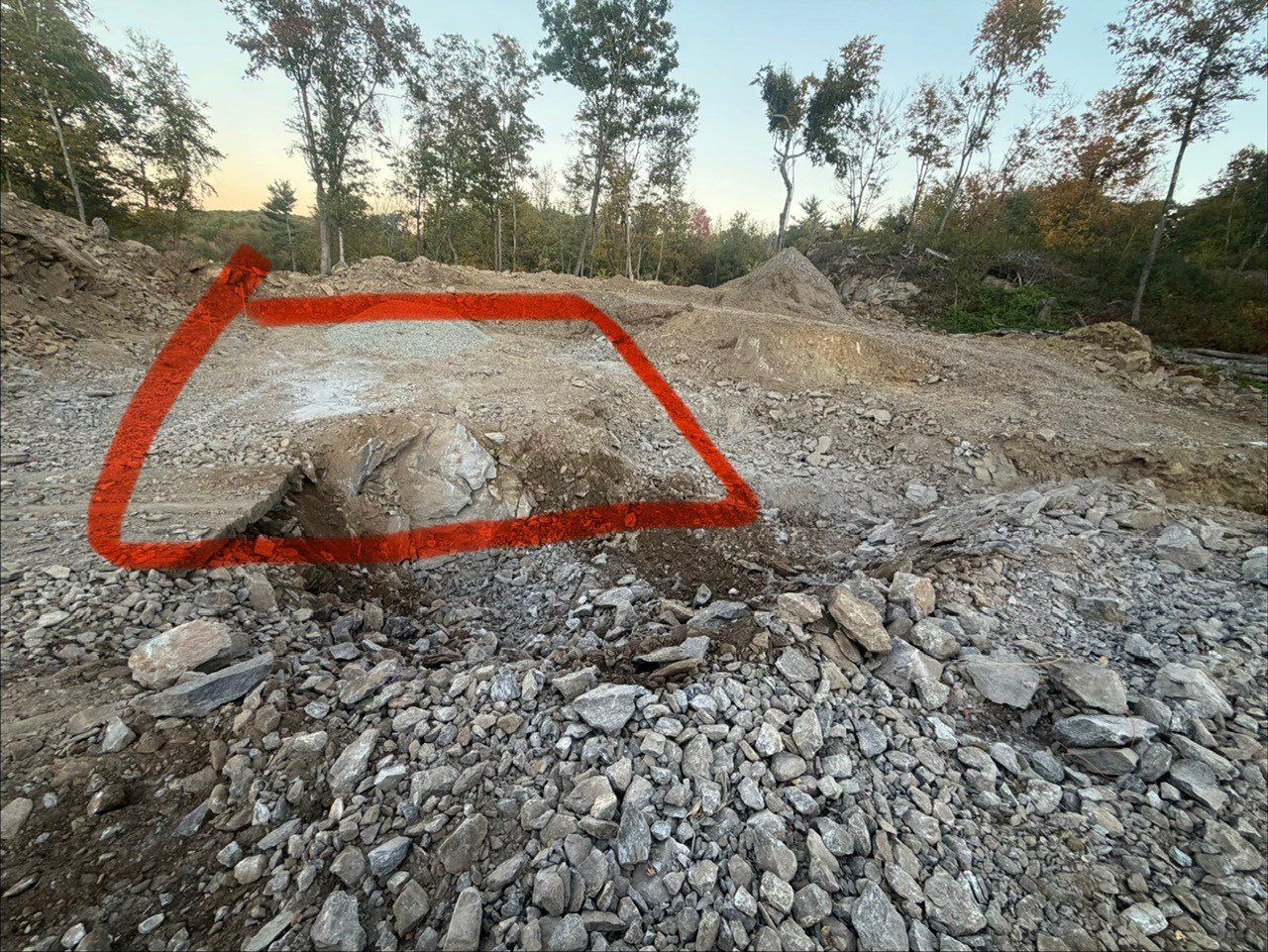
A new house on a lot in Barkhamsted that had just been blasted out of granite, and a straight answer on one question before the footings were formed: what goes under them. The rock along most of the footing lines was a few inches below where the footing bottoms would be, the site contractor had started spreading clean stone, and in one place, at the rear wall, the rock dropped away into a pocket about four feet deep. The town wanted a letter.
Then the scope grew. Another engineer had sized the steel beams, a column and two footings for the owner, and he wanted changes: shallower beams for headroom, a different post layout, and the kitchen beam run the full length of the bump-out. He asked me to take over the steel, redesign it the way he wanted it, and carry the whole package under my seal. All of it from my desk.
What we found
I did not set foot on the site, so the letter says what it stands on. The owner walked the footing lines and photographed along each one from the corners, put a tape in the deep pocket, lettered the corners on a copy of the foundation plan and wrote the depth from footing bottom to undisturbed ground along each wall. Then he wrote that the pocket had been cleaned out and bottomed on bedrock a few inches below the 44 in he had measured.
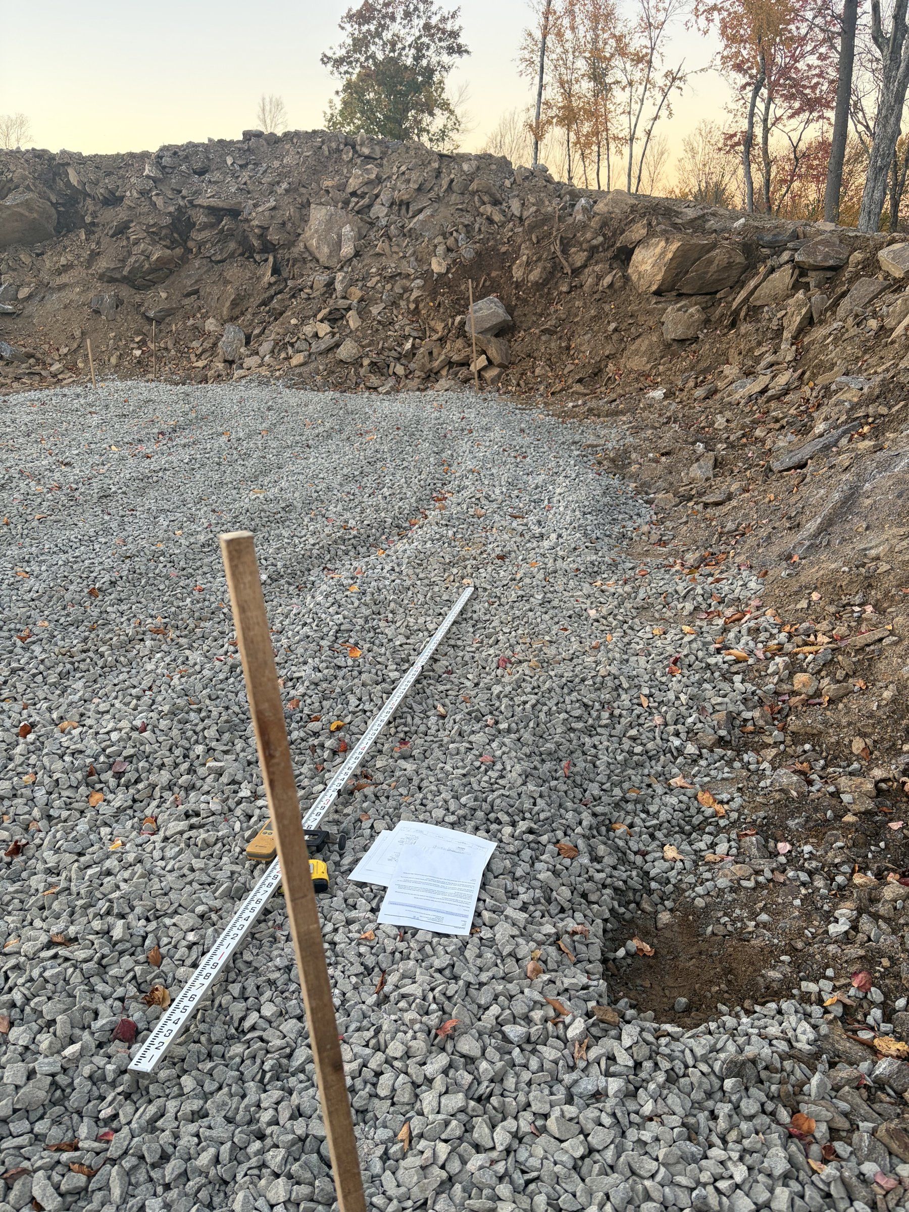
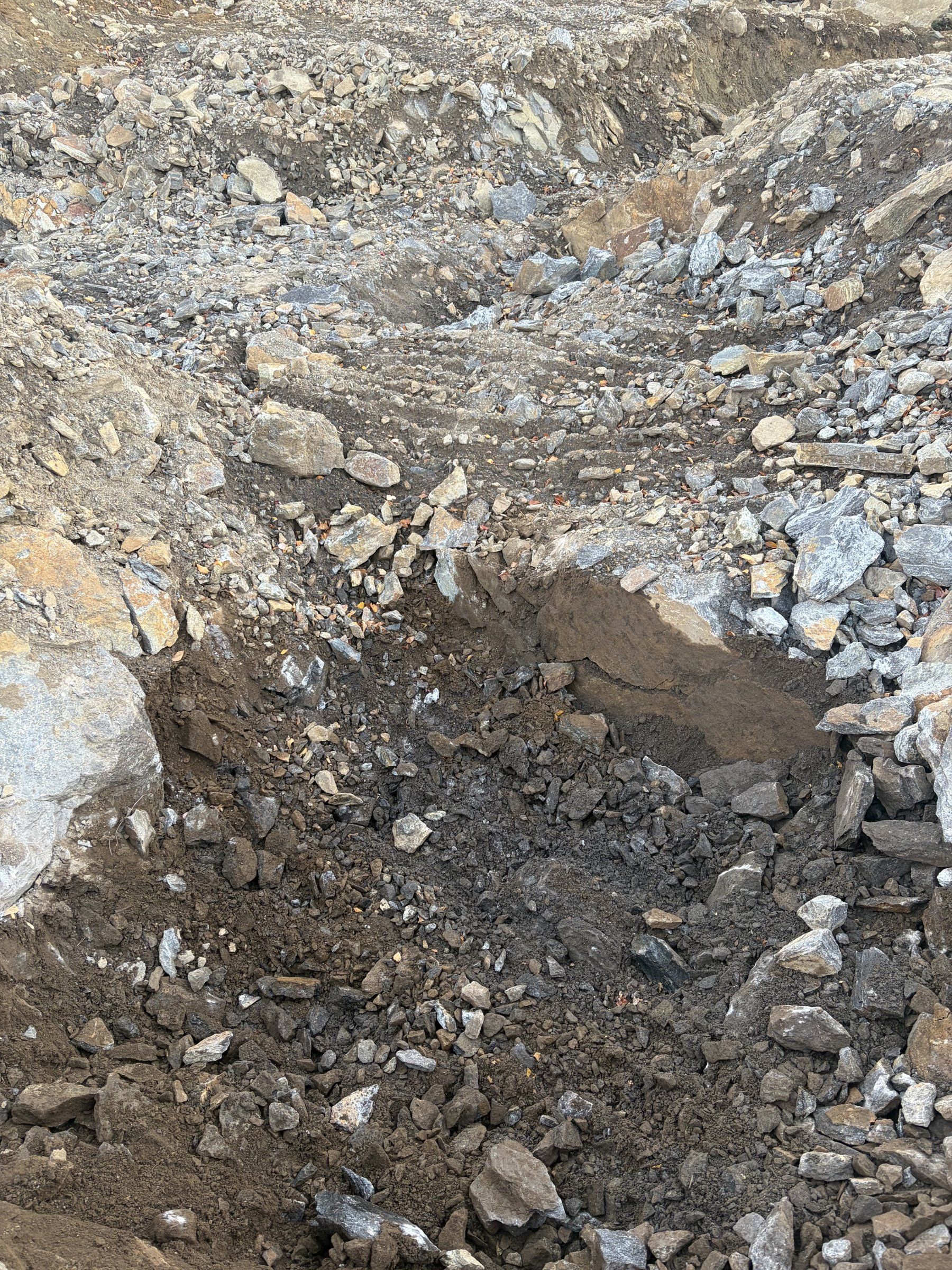
What they showed was a blasted granite site with the rock fairly flat along the lines: bedrock 3 to 8 in below the footing bottom along the right wall, ground he described as soil or rock 3 to 8 in below it along the others, and one pocket at the rear wall about 11 ft by 6 ft and about 4 ft deep. The pocket sat directly under the pier between the two garage doors. That is where the center beam’s rear post comes down onto the frost wall. Water stood three or four inches deep in it after heavy rain, and a curtain drain ran to daylight from the corner above the bottom of the pocket.
What goes under the footings?
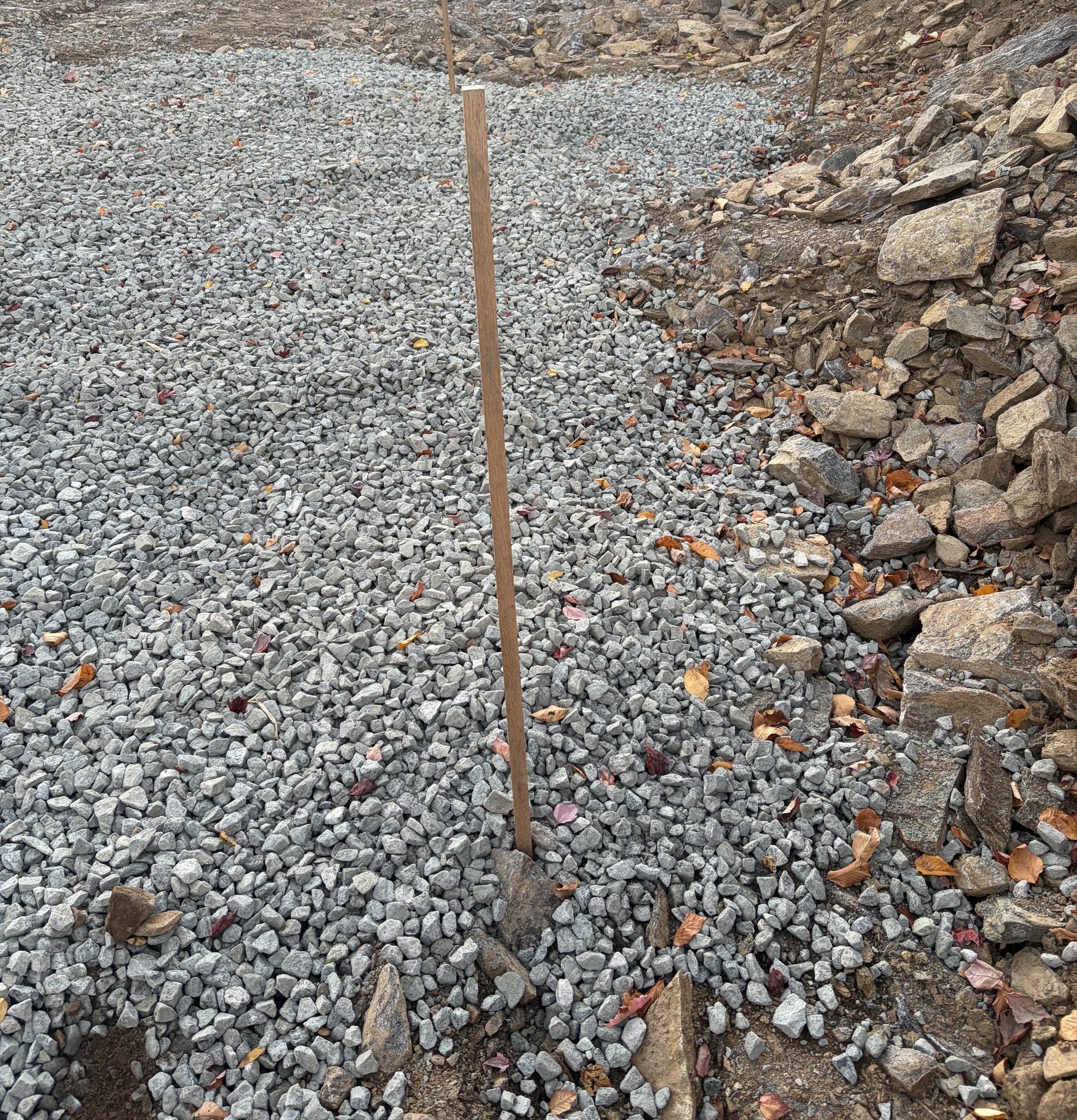
The footings bear on a bed of compacted crushed stone placed on the cleaned rock, which the Connecticut code allows as engineered fill. Before any stone goes in, the loose and shattered rock left by the blasting comes off, and topsoil, clay, silt and standing water come out. The letter spells out how to build it so a site crew can follow it: clean angular stone, 3/4 to 1-1/2 in with no fines; lifts no thicker than 8 in loose; a vibratory plate or roller with the vibration on, at least four passes, until the stone stops moving; at least 4 in thick after compaction and never more than 24; at least 12 in past each footing face, held on a 1 to 1 shoulder wherever the rock falls away so the stone never ends at a free face. A static drum roller alone does not compact clean stone; the vibration does the work. Where sound rock is at the footing bottom or within 4 in of it, the footing is poured down onto the rock instead. The bed is checked at 3,000 psf, half the code’s value for gravel, and the highest pressure anywhere in the package is about 2,450 psf, at the bump-out corners with the girder truss bound on them, about 2,500 at one corner once the stair was added on SK-1, so the stone governs and the ground under it never does.
The pocket gets 3,000 psi concrete, the footing mix, placed on the cleaned rock after the water is pumped out and brought up to the footing bottom, about 10 cubic yards, no forms and no bars. The continuous footing is then built on top of it as a separate pour.
The engineering
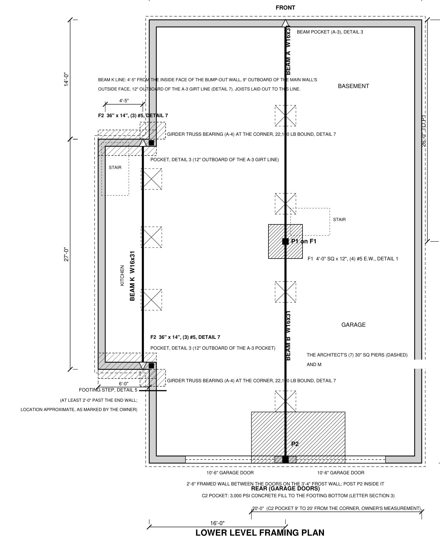
The steel came out as three W16x31 beams. Two on the center line, each about 26 ft, meeting end to end on one HSS 4x4 post at the middle of the house, the front end in a pocket in the gable wall and the rear end on a second post standing on the frost wall inside the framed wall between the garage doors, so no beam lands on wood at the rear. And one on the kitchen line, running the full length of the bump-out from pocket to pocket. The owner had asked for steel the full length with a post at the end of the stairs. The same beam that works on the center line spans the whole bump-out without it, so the post, its footing and 4 ft of leftover wood girder all went away. The beams are 16 in deep against the 24 in of the scheme they replace, with the top of steel 1-1/2 in below the joists and a 2x6 nailer on the flange. The center beams deliver about 17,300 lb to each end and the kitchen beam about 15,000, service loads, and the center post carries about 34,600 lb.
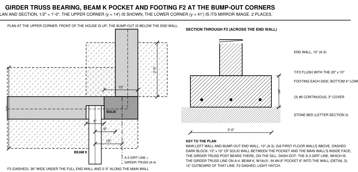
The corners were the hard part. The roof over the kitchen bump-out is carried by a girder truss along the main wall line, and the two ends of that girder bear on the bump-out’s end walls at the corners. The trusses are not designed yet, so the letter takes that reaction at 22,100 lb a side, a bound built from the drawings with the roof, the snow, the attic floor and the bump-out roof all on it at once. The girder’s post comes down the main wall onto the sill at each corner, exactly where the architect’s pocket for the kitchen beam would have cut the wall. So the kitchen beam moved 12 in outboard and both pockets with it, and the post stands on 15 in of solid wall beside the pocket. Even so, the kitchen beam end and the girder post together put about 37,100 lb within a foot of wall at each corner. The 20 in footing carries that only if the 10 ft wall is credited with spreading it at 45 degrees, and I was not willing to lean on that at both corners. Footing F2 is 36 in wide and 14 in thick under the full length of each end wall and 2 ft along the main wall past it, with three #5 bars the long way lapped into the footing on either side, bearing at about 2,450 psf with the whole corner on it.
One thing came off the drawings, too. Earlier in the job I had described a widened footing under the pier between the garage doors, sized for the 34,500 lb the deeper beam scheme brought to that pier. With the W16 pair the load there is about 22,200 lb, the pier bears at about 2,230 psf on the 20 in footing that runs around the house, and the widening was withdrawn in writing.
The letter closes with what it does not change, which is almost everything else on the architect’s foundation sheet, and with one condition that matters: the truss supplier’s layout comes to this office before the trusses are ordered, because a truss design that bears on either beam line, or puts more than 22,100 lb on the girder’s ends, is a change to this design.
How it got delivered
The job came in on a Monday by email and phone. The owner sent his photographs and his lettered plan two days later, and he had the stone answer by email within the week. When the scope grew to the steel, I gave him a date for the whole package and the letter, sheet S-1 and sheet S-2 were signed and sealed on that date.
That same morning he wrote back: his stairs land on the kitchen beam, and would I look. Cutting the I-joists in the stair band short onto a header is an ordinary stair opening, but where the stringers meet the steel it wanted a detail. The stamped one-sheet stair detail at the beam went out that afternoon, inside the fee. It was ours to catch, so it was ours to fix.
If you are building on ledge in the Litchfield hills and the question is what goes under the footings, or you have a set of beams you want a second look at before the steel is ordered, call me. A remote job like this one takes your photographs and your tape, and the stone question here was answered within the week.
Structural Details
| Item | Detail |
|---|---|
| Building | New wood-frame single-family house, about 32 ft wide by 52 ft long, with a kitchen bump-out on one side and a two-car garage in the lower level at the rear, on a blasted granite lot |
| Framing | Main floor on 11-7/8 in I-joists spanning the 32 ft direction to the two long walls and a center beam line, and in the bump-out to a kitchen beam line as well. Pre-engineered attic trusses spanning the 32 ft between the long walls, with a girder truss along the main wall line over the kitchen bump-out |
| Foundation | 10 in poured concrete basement walls on 20 x 10 in continuous footings, stepping down to a 3 ft 4 in frost wall at the garage, all on a bed of compacted crushed stone placed on the cleaned rock |
| Existing condition | A blasted site. Bedrock 3 to 8 in below the footing bottom along the right wall and ground the owner described as soil or rock 3 to 8 in below it along the other lines, and one pocket at the rear wall, about 11 ft by 6 ft and about 4 ft deep to bedrock, directly under the pier between the garage doors. Three to four inches of water standing in it after heavy rain |
| Scope | Three things in one package. How to build the stone bed under the footings and what goes in the deep pocket. Three W16x31 beams and two steel posts replacing the deeper beams, column and isolated footings a prior engineer had sized, carried under this office's seal. And the footings under the new steel, the bump-out corners most of all, with a footing step detail. Plus a one-sheet stamped stair detail the day the package went out |
| Stone bed | 4 to 24 in compacted, 3/4 to 1-1/2 in clean angular stone, 8 in loose lifts, vibratory compaction, at least 12 in past each footing face |
| The pocket at the rear wall | About 11 ft by 6 ft, about 4 ft to bedrock, filled with 3,000 psi concrete to the footing bottom, roughly 10 cubic yards |
| Bearing on the bed | Held to 3,000 psf, half the code's gravel value. The highest pressure in the package is about 2,450 psf, at the bump-out corners with the girder truss bound on them, about 2,500 at one corner once the stair was added on SK-1 |
| Beam end reactions, service | About 17,300 lb at each end of the center beams, about 15,000 lb at each end of the kitchen beam |
| Center post, service | About 34,600 lb |
| Girder truss end reaction, bound | 22,100 lb at each end, built from the drawings with roof, snow, attic floor and bump-out roof all on it, until the truss supplier's layout is checked against it |
| Load at each bump-out corner | About 37,100 lb within a foot of wall, the kitchen beam end and the girder truss post together, with the girder at its bound |
| Center beam line | Two W16x31, ASTM A992, each about 26 ft, joined end to end on one post at the middle of the house. The front end in the beam pocket in the front gable wall, the rear end on a post inside the framed wall between the garage doors |
| Kitchen beam line | One W16x31, about 26 ft, pocket to pocket the full length of the bump-out, no post, set 12 in outboard of the line the architect drew so the pockets clear the girder truss posts at the corners |
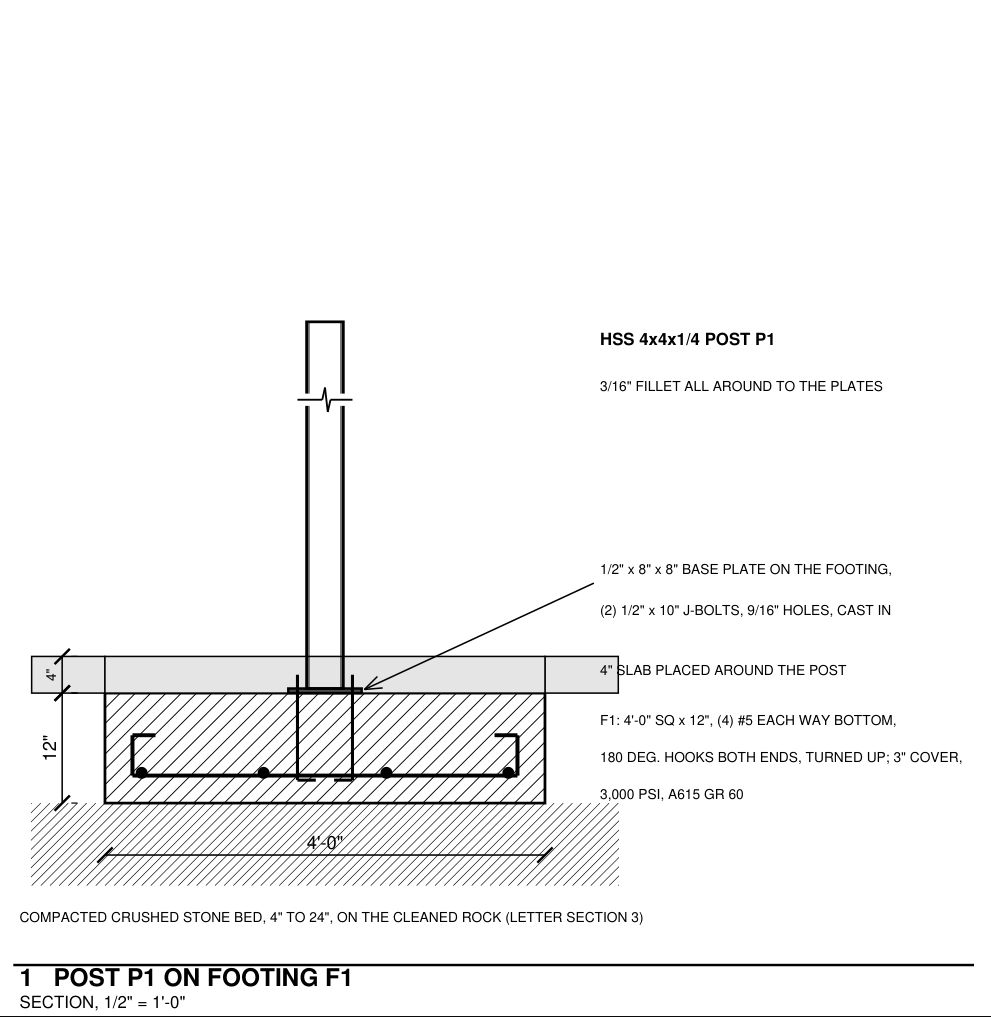
| Posts P1 and P2 | HSS 4x4x1/4 with 1/2 in cap and base plates, bolted to the beams and anchored to the concrete |
| Footing F1 under the center post | 4 ft square by 12 in thick, four #5 bars each way in the bottom, hooked both ends, 3,000 psi, top 4 in below the slab, on the stone bed |
| Footing F2 at each bump-out corner | 36 in wide by 14 in thick under the full end wall and 2 ft along the main wall, three #5 bars the long way lapped 2 ft into the 20 in footing, top flush with the footing beside it |
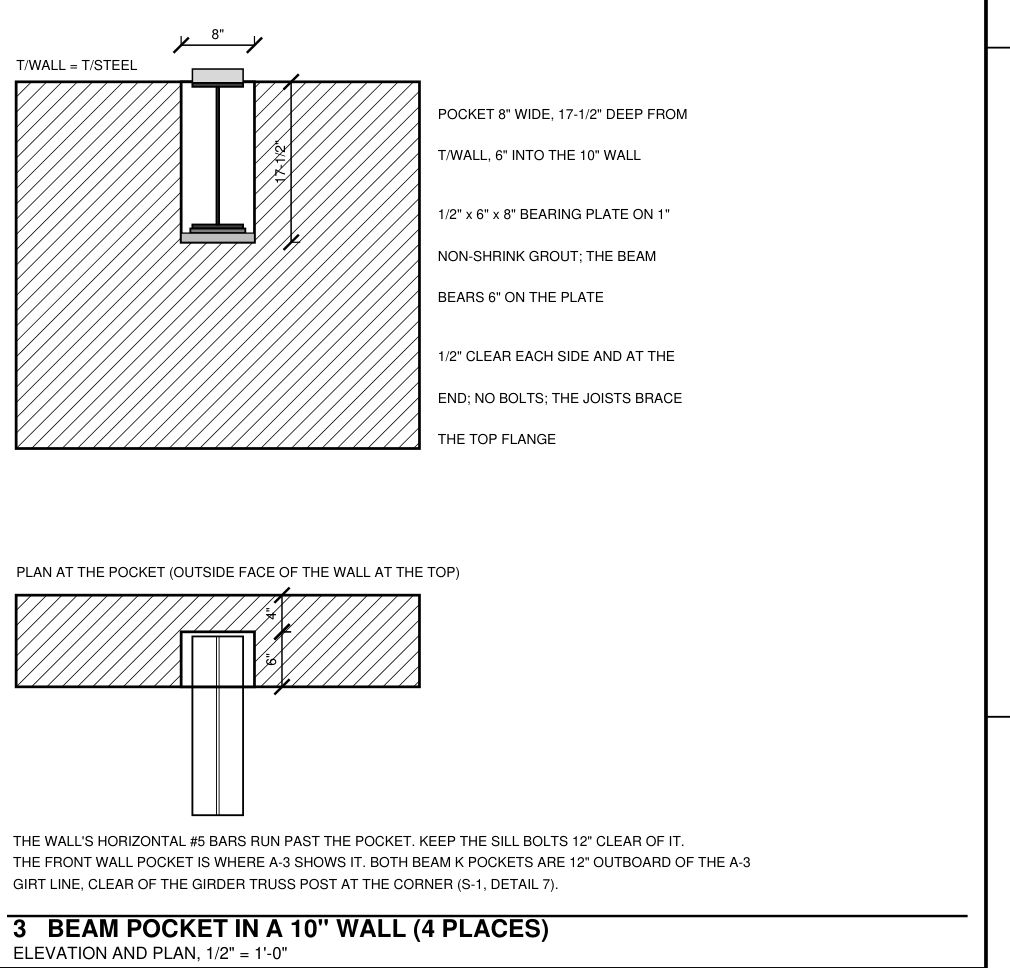
| Beam pockets | 6 in of bearing on a 1/2 in steel plate set in grout, 1/2 in clear each side and at the end, a 2x6 nailer bolted to the top flange for the joists |
| Footing step | Steps not more than 2 ft high and not less than 2 ft long, wall and footing concrete placed together at the step, the two #5 bars carried through and lapped 2 ft, the lower bottom at least 42 in below grade |
| Load path | The trusses carry the roof and the attic floor to the two long walls. Over the kitchen a girder truss carries them along the main wall line to the bump-out's end walls at the corners. The I-joists carry the main floor to the long walls and the center beam line, and in the bump-out to the kitchen beam too. The beams carry the first floor only, out to their pockets in the walls and down the posts. Every footing bears on a compacted stone bed on the cleaned rock, directly on the rock where it is within 4 in, or on the concrete that fills the pocket, and the bed is held to 3,000 psf so the ground under it never governs |
| Loads carried | first floor at 40 psf live and 20 psf dead, first-floor partitions along the center line, roof, snow, attic floor and the bump-out roof, through the girder truss at its 22,100 lb bound |
| Code basis | Connecticut State Building Code (2022), engineered fill under footings and presumptive bearing values; ASTM A992 wide flanges and A500 HSS, AISC 360 |
Alternatives Considered
- A widened footing under the pier between the garage doors, sized earlier for the 34,500 lb the deeper beam scheme brought to that pier. With the W16 pair the load there fell to about 22,200 lb, the 20 in footing carries it at about 2,230 psf, and the widening was withdrawn
- The owner asked for steel the full length of the kitchen bump-out with a post at the end of the stairs. The same W16x31 that works on the center line spans the whole bump-out without the post, so the post, its footing and 4 ft of leftover wood girder all went away
- A 16 in deep beam against the 24 in deep W24x62 it replaces, with the top of steel 1-1/2 in below the joists and a nailer on the flange, for headroom in the lower level
- Where sound rock sits at the footing bottom or within 4 in of it, pour the footing to the cleaned rock instead of setting it on a thin layer of stone. Where the rock is more than 24 in down, concrete fill, not more stone
Drawings and Details
Drawings
Before
What the Review Found
- The deep pocket, the one place on the site where the rock dropped away, lay directly under the pier between the garage doors, where the center beam's rear post comes down
- The girder truss over the kitchen bears at the bump-out's end walls exactly where the architect's beam pocket would have cut the wall. The kitchen beam moved 12 in outboard, both pockets with it, and the truss post stands on 15 in of solid wall beside the pocket
- With the girder truss taken at its 22,100 lb bound, the two bump-out corners carry about 37,100 lb within a foot of wall each. The 20 in footing only works there if the 10 ft wall is credited with a full 45 degree spread, so the footing widens to 36 in at both corners instead
- No truss or girder may bear on either beam line. The truss supplier's layout comes to this office before the trusses are ordered, so the girder and its bearing can be checked against it
- After delivery the owner noticed his stairs landed on the kitchen beam. A stamped one-sheet detail for the stair at the beam went out the same afternoon, inside the fee, because it was ours to catch
Questions About This Project
Can footings sit on crushed stone instead of soil or rock?
Yes, when an engineer specifies the stone and how it is placed, and the ground under it is rock or firm native ground. Clean angular crushed stone with no fines, placed in lifts and compacted with a vibratory plate or roller, is engineered fill under the Connecticut code. It levels a blasted surface, it drains, and it does not heave. Rounded gravel and bank run with fines are not the same thing and are not acceptable.
Why fill a deep spot with concrete instead of more stone?
Because the deeper a stone bed is, the harder it is to compact it all the way through and the more it can move. The package caps the bed at 24 in. Where the rock is farther down than that, footing concrete placed against the rock fills the gap, and the footing is poured on top of it as a separate pour.
The steel was already sized. Why did it change?
The owner wanted shallower beams, a different post layout and one less post at the stairs, and he asked me to take over the steel and put my seal on it. A 16 in beam that carries the floor at the code's deflection limits is a reasonable trade for headroom, and the lighter beam also brought the load at the garage-door pier down enough to cancel a widened footing I had described earlier.
Planning Something Similar in Barkhamsted?
Call or text Travis at (860) 519-6009, or send the details below. Stamped letters follow within a few business days of the visit, and you always talk to the engineer who stamps it.
This page describes engineering performed for a specific structure, reviewed from drawings and photographs. Spans, member sizes, and connection details are particular to that building and its loading. Nothing here is a design for any other structure. Every project requires its own analysis by a licensed engineer.